State Space Analysis of Control System


Before I introduce you about the concept of state space analysis of control system, it is very important to discuss here the differences between the conventional theory of control system and modern theory of control system.
The conventional control theory is completely based on the frequency domain approach while the modern control system theory is based on time domain approach.
In the conventional theory of control system we have linear and time invariant single input single output (SISO) systems only but with the help of theory of modern control system we can easily do the analysis of even non linear and time variant multiple inputs multiple outputs (MIMO) systems also.
In the modern theory of control system the stability analysis and time response analysis can be done by both graphical and analytically method very easily.
Now state space analysis of control system is based on the modern theory which is applicable to all types of systems like single input single output systems, multiple inputs and multiple outputs systems, linear and non linear systems, time varying and time invariant systems. Let us consider few basic terms related to state space analysis of modern theory of control systems.
State in State Space Analysis : It refers to smallest set of variables whose knowledge at t = t0 together with the knowledge of input for t ≥ t0 gives the complete knowledge of the behavior of the system at any time t ≥ t0.
State Variables in State Space analysis : It refers to the smallest set of variables which help us to determine the state of the dynamic system. State variables are defined by x1(t), x2(t)……..Xn(t).
State Vector : Suppose there is a requirement of n state variables in order to describe the complete behavior of the given system, then these n state variables are considered to be n components of a vector x(t). Such a vector is known as state vector.
State Space : It refers to the n dimensional space which has x1 axis, x2 axis ………xn axis.
State Space Equations
Let us derive state space equations for the system which is linear and time invariant.
Let us consider multiple inputs and multiple outputs system which has r inputs and m outputs.
Where, r = u1, u2, u3 ……….. ur.
And m = y1, y2 ……….. ym.
Now we are taking n state variables to describe the given system hence n = x1, x2, ……….. xn.
Also we define input and output vectors as,
Transpose of input vectors,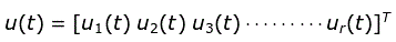
Where, T is transpose of the matrix.
Transpose of output vectors,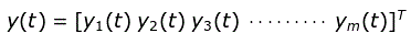
Where, T is transpose of the matrix.
Transpose of state vectors,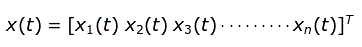
Where, T is transpose of the matrix.
These variables are related by a set of equations which are written below and are known as state space equations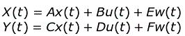
Representation of State Model using Transfer Function
Decomposition : It is defined as the process of obtaining the state model from the given transfer function. Now we can decompose the transfer function using three different ways:
Direct decomposition,
Cascade or series decomposition,
Parallel decomposition.
In all the above decomposition methods we first convert the given transfer function into the differential equations which is also called the dynamic equations. After converting into differential equations we will take inverse Laplace transform of the above equation then corresponding to the type of decomposition we can create model. We can represent any type of transfer function in state model. We have various types of model like electrical model, mechanical model etc.
Expression of Transfer Matrix in terms of A, B, C and D. We define transfer matrix as the Laplace transform of output to the Laplace transform of input.
On writing the state equations again and taking the Laplace transform of both the state equation (assuming initial conditions equal to zero) we have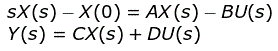
We can write the equation as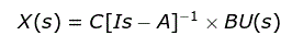
Where, I is an identity matrix.
Now substituting the value of X(s) in the equation Y(s) and putting D = 0 (means is a null matrix) we have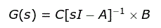
Inverse of matrix can substitute by adj of matrix divided by the determinant of the matrix, now on rewriting the expression we have of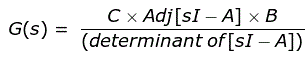
|sI-A| is also known as characteristic equation when equated to zero.
Concept of Eigen Values and Eigen Vectors
The roots of characteristic equation that we have described above are known as eigen values or eigen values of matrix A.
Now there are some properties related to eigen values and these properties are written below-
Any square matrix A and its transpose At have the same eigen values.
Sum of eigen values of any matrix A is equal to the trace of the matrix A.
Product of the eigen values of any matrix A is equal to the determinant of the matrix A.
If we multiply a scalar quantity to matrix A then the eigen values are also get multiplied by the same value of scalar.
If we inverse the given matrix A then its eigen values are also get inverses.
If all the elements of the matrix are real then the eigen values corresponding to that matrix are either real or exists in complex conjugate pair.
Now there exists one eigen vector corresponding to one Eigen value, if it satisfy the following condition (ek × I – A)Pk = 0. Where, k = 1, 2, 3, ……..n.
State Transition Matrix and Zero State Response
We are here interested in deriving the expressions for the state transition matrix and zero state response. Again taking the state equations that we have derived above and taking their Laplace transformation we have,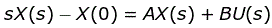
Now on rewriting the above equation we have
Let [sI-A]-1 = θ(s) and taking the inverse Laplace of the above equation we have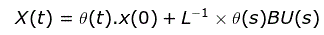
The expression θ(t) is known as state transition matrix.
L-1.θ(t)BU(s) = zero state response.
Now let us discuss some of the properties of the state transition matrix.
If we substitute t = 0 in the above equation then we will get 1. Mathematically we can write θ(0) =1.
If we substitute t = -t in the θ(t) then we will get inverse of θ(t). Mathematically we can write θ(-t) = [θ(t)]-1.
We also another important property [θ(t)]n = θ(nt).
Statement: Respect the original, good articles worth sharing, if there is infringement please contact delete.
Electrical4U is dedicated to the teaching and sharing of all things related to electrical and electronics engineering.


