During actual operation, pad - mounted transformers face typical heat - related problems:
- High - temp/high - load trips: Prone to tripping under sustained high - temperature, high - load conditions.
- Fan & thermostat failures: Long - term fan use causes malfunctions, damaging thermostats and blocking hot - air discharge, disrupting operation.
- Poor fan placement: Mounting fans on the cabinet top forces power - off maintenance/ replacement; this layout also traps heat, raising indoor temps to scald - risk levels.
To optimize heat dissipation, this paper uses finite element analysis to build a 3D transformer model. By mapping temperature field distributions, it identifies overheating hotspots and refines the cooling system design.
1. Temperature Field Basics
A temperature field describes spatial - temporal temperature variations, with heat generation, transfer, and distribution tightly coupled. For pad - mounted transformers, heat originates in cores, windings, etc. Operating conditions/durations alter heat patterns, and multi - medium interactions (cores, windings, insulation) create uneven temperature distributions.
Heat transfers via conduction (dominant, driving heat from windings/cores through insulating resin to ambient air) and convection. Conduction intensity correlates with temperature gradients—heat moves from hot components to cooler resin, then dissipates into external air. Heat flux calculations follow:

In the formula: q represents the heat flux density;λ represents the thermal conductivity; ∂t/∂x is the temperature gradient, reflecting the rate of temperature change with distance; n is the heat conversion coefficient. When there are temperature differences at different positions, heat mainly circulates to balance the temperature, and this state of temperature balance is heat convection. During the operation of a pad - mounted transformer, the heat generated by various parts will come into contact with air and transfer between them, causing changes in the temperature of the surrounding gas. During this process, heat transfer is achieved through heat convection, which can be expressed by the following formula:

In the formula, h is the convective heat transfer coefficient, tf represents the fluid temperature, and tw represents the temperature of the objects surface. When the temperature of an object is higher than absolute zero, radiant heat will be generated, usually called thermal radiation. With other factors remaining unchanged, the amount of radiation generated between objects will change as the temperature rises (with the temperature maintaining a continuous upward trend). During the operation of a pad - mounted transformer, the equipment itself does not come into direct contact with thermal radiation; when the temperature of the transformer stabilizes, its thermal radiation function will achieve heat dissipation through thermal radiation, and this process can be expressed by the following formula:

In the formula, S denotes the radiation surface area, T is the thermodynamic temperature of the object, and σ is the radiation constant. When designing the heat dissipation system for pad - mounted transformers, the finite element analysis (FEA) method is primarily employed to establish thermal equilibrium equations. Through calculations, the temperature at each node of the object can be determined. This is particularly useful for measuring temperature points that are difficult to obtain in practice, identifying optimal hotspot locations, and then conducting coupling analysis. The core principles of decomposing the temperature field using FEA are as follows:
- Discretize the three - dimensional physical domain;
- Use functions to describe the temperature variations at any node within the element;
- Construct element equations;
- Assemble the elements and apply external excitations at the nodes;
- Solve the equations by considering the temperature field boundary conditions;
- Calculate the temperature rise at each node;
- Derive the element temperature rise based on the temperature field equations.
2 Modeling and Temperature Field Simulation of Pad - Mounted Transformers
2.1 Finite Element Modeling
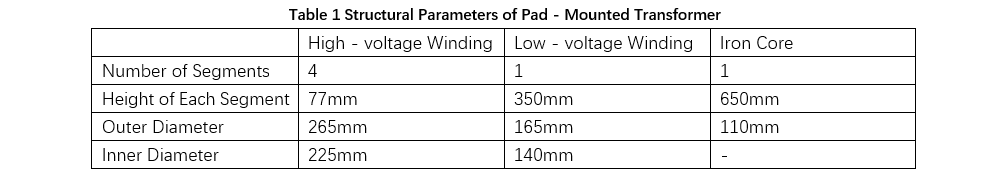
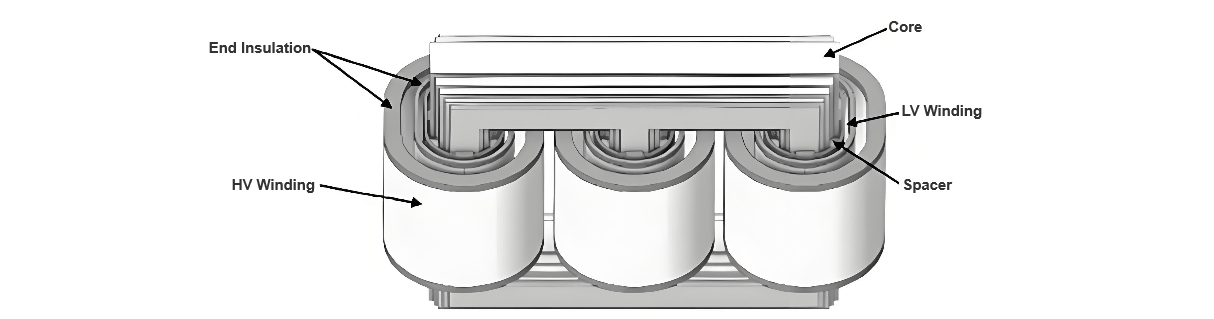
Table 1 lists the relevant parameters of the pad - mounted transformer selected in this paper. A finite element model is constructed based on these parameters. Subsequently, simplified models are established for the high - voltage winding, low - voltage winding, and iron core of the pad - mounted transformer.
During model construction, since the welded connections of the high - voltage winding outlet terminals are relatively firm, they are not taken into account in the initial design phase. For simplification, the iron core is modeled as a monolithic structure, with inter - laminar gaps ignored (these gaps are addressed by means of the properties of bulk silicon steel to account for the material conductivity). The 3D simulation model of the transformer is shown in Figure 1.
To analyze the effects of natural convection on heat dissipation, an external air domain (with dimensions of 5000mm×5000mm×3000mm) is added to the simulation environment, enabling realistic modeling of the airflow patterns around the transformer.
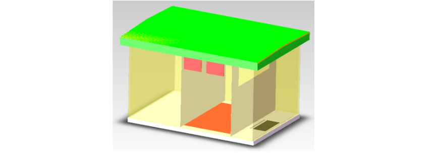
2.2 Enclosure Model of Pad-Mounted Transformer
The windings and iron core are modeled as heat sources, with their heat generation rates calculated based on transformer design parameters. The air domain is configured with pressure outlets at the top and inlets distributed along the bottom and sides, maintaining an ambient temperature set at 300K. During simulations, natural convection parameters are derived by selecting an appropriate turbulence model based on the Rayleigh number.
The enclosure geometry (Figure 2) is simplified due to its complex composite structure. The roof's perforated panels are neglected, treating the entire roof as a continuous air domain. Porous media are placed at the air outlets under the eaves to simulate flow resistance. The air domain around the enclosure's bottom support beams is considered interconnected. An additional 155mm - high air layer is added beneath the enclosure to account for the foundation's impact on heat dissipation.
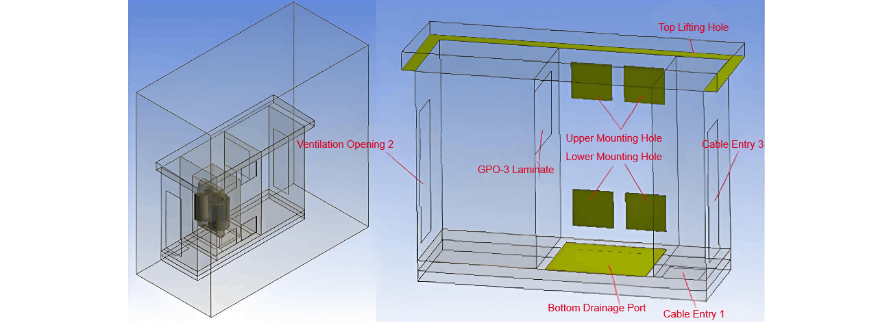
In the established model, the pre - set bottom holes, top holes, and upper - lower holes all belong to porous media, with a thickness of 10 mm (such as the yellow - green block in Figure 3), thus simulating the mesh plate. The specification of the bottom hole is 1450 × 1200 mm², and the specification of the upper - lower holes is 550 × 500 mm². Three openings and an epoxy plate are also set in the model, and the openings are determined to be in an open or closed state according to the actual situation. Generally, if the floor - mounted type is adopted, the top hole, the epoxy plate, and Opening 1 are in an open state; if the bottom - holed type is adopted, the top hole, the bottom hole, and Openings 1/2/3 are all in an open state.
2.3 Temperature Field Distribution Analysis
Next, a finite element model is built by meshing the geometric model. Ensure unity of natural convection and internal mesh models, and refine meshing at enclosure holes and air interfaces to improve calculation accuracy. Based on the geometric model, the finite element model has 401,856 nodes and 518,647 meshes. Key settings for the pad - mounted transformer model:
- Fluid - structure interface: Air interface, no - slip state for heat conservation.
- Adiabatic surfaces: Top of the roof, sides of bottom support beams, and external air.
- Heat - conducting surfaces: Enclosure sides (1mm - thick steel plate), all enclosure walls (2mm - thick steel plate), with upper holes open and lower holes closed.
Using finite element software, the temperature field model shows: Windings have the highest temperature in the transformer, followed by the iron core; adjacent air temperature is also high, decreasing during air rise until matching ambient temperature at the pressure outlet. During operation, hot air expansion causes air accumulation and collisions between ambient and duct air (due to continuous heating and volume increase). Air viscosity affects duct flow and the flow field. Hot air accelerates near the ground and slows away; airflow - surface contact forms a thermal boundary layer, which, due to its thickness, reduces heat transfer coefficients, increasing temperature and air viscosity while decreasing flow velocity. Hot air alters the temperature above the transformer, with temperature proportional to thermal radiation.
3 Heat Dissipation Design of Pad - Mounted Transformers
3.1 Model Analysis
Pad - mounted transformers are arranged inside enclosures with a high safety level. To ensure smooth air circulation within the enclosure and give full play to the transformer's heat dissipation performance, axial flow fans need to be configured to discharge hot air from the equipment interior. Meanwhile, heat sinks are installed outside the enclosure to achieve heat exchange. Through heat exchange, the continuous circulation of air inside the transformer can be promoted.
During the operation of pad - mounted transformers, heat is mainly generated by windings and iron cores. Therefore, the design needs to focus on the air flow states of these two components and integrate the relevant elements for building the heat dissipation model.
3.2 Determination of Model Parameters
For pad - mounted transformers, the differences between indoor air parameters and temperature performance parameters are relatively small. When selecting silicon steel sheets, their heat resistance performance should be prioritized. Meanwhile, the numerical ratio of copper wires to insulating resin is analyzed to determine the thermal performance parameters.
3.3 Condition Setting
The average pressure at the air inlet and outlet of the pad - mounted transformer is one atmospheric pressure. Combined with the performance of the heat sink, the temperature of cold air is taken as the inlet condition to establish a finite element model, and the symmetry plane and air inlet - outlet direction are defined.
3.4 Result Analysis
After establishing the model and setting the boundary conditions, calculations are carried out. The analysis shows that the air outlet of the pad - mounted transformer is the hottest point, with a temperature reaching 394.5K (corresponding to a hot - spot temperature of 120.5℃). The hottest point of the iron core is far from the air outlet, and the calculated hot - spot temperature is 110℃. Moreover, the positions close to the air inlets and outlets have poor heat dissipation performance.
3.5 Inlet and Outlet Air Analysis
Simulate the change of air flow velocity: If the hot high - voltage winding is built - in close to the air outlet and the air outlet has a right - angle structure, it will affect the air pressure, making the air inside the encapsulation thin and unfavorable for heat dissipation.
Based on this, optimize the air outlet design: Move the air outlet upward by about 30cm, keep the height unchanged, and simultaneously reduce the width of the air inlet (mainly reduce by 10cm), so that the overall length of the enclosure increases by 20cm. After calculation, under this scheme, the hot - spot temperature and average temperature of the winding decrease significantly. Analyzing the air flow field velocity distribution, the winding air flow shows a 120° angle when transferred to the air outlet, indicating that the air flow is smooth.
3.6 Summary
Pad - mounted transformers play a crucial role in the power distribution system. If the large amount of heat generated during operation cannot be dissipated in a timely manner, it is likely to cause failures and threaten the stability of the system. Designers need to deeply analyze the heat dissipation problems of pad - mounted transformers, combine with the changes of the temperature field, use scientific methods such as the finite element method to build heat dissipation models, optimize the equipment's heat dissipation system, and improve the overall heat dissipation efficiency.