Medium Voltage DC Solid-State Circuit Breakers Design and future
How medium voltage solid-state circuit breaker work:
A solid-state DC breaker uses power semiconductors to interrupt the fault current. A simple topology of a solid-state DC breaker is shown in Figure. 1. Four diodes and an IGCT represent the main conduction path, while the surge arrester is used to discharge the line inductance in case of a fault. When the DC breaker is tripped, the IGCT is turned off. Due to the inductively stored energy, the voltage across the semiconductors rises quickly and the surge arrester starts conducting current. In order to discharge the line inductance, the protection voltage of the surge arrester must be higher than the nominal grid voltage. Also, it must be ensured that the power semiconductors are able to withstand the protection voltage of the surge arrester. The main advantage of a solid-state DC breaker is its fast interruption speed and the lack of moving parts. Since the power semiconductors are placed in the main conduction path, on-state losses occur.

Figure 1:Simple design of solid stat circuit breaker
Solid-state circuit breakers rely solely on the solid-state switch to carry the nominal load and to interrupt current. Because the electric arc is eliminated, another mechanism is needed to dissipate the stored energy in circuit inductance. This is often achieved via a parallel-connected metal-oxide varistor (MOV). A MOV has a non-linear voltage/current characteristic.
Its resistance remains high (effectively acting as an open circuit) until the voltage across it reaches a certain value, where its resistance drops allowing current to conduct through the device. When conducting a MOV also clamps the voltage across it at a constant value.
This type of device is frequently used in high voltage systems as a surge arrester and is also used as a protection device for voltage-sensitive components.
Two bi-directional solid-state circuit breaker topologies are shown in Figure 2. When the breaker is closed, both semiconductor devices are turned on, allowing current to flow in both directions. During the current interruption, both devices are turned off, forcing the voltage across the devices to rise until the MOV starts to conduct and clamp the voltage across the devices.The conducting MOV acts to dissipate the energy stored within the circuit inductance.
While IGCTs are shown in Figure 2 (a), GTOs have also been used in older designs based on the same circuit topology.

Figure 2 a) IGCT based simple bi-directional solid-state circuit breaker, (b) IGBT based simple bi-directional solid-state circuit breaker
Figure 3 shows a number of alternative designs which apply this concept to medium voltage systems. In these systems, multiple devices are connected in series to increase the total voltage withstand capability of the solid-state breaker. Diodes are also often connected in series with the main breaking switches to improve the reverse block voltage of the system, due to the limited reverse blocking capability of existing devices such as IGCT and GTO. The circuit is shown in Figure 3 (c) includes parallel-connected RC snubbers which are required for GTO-based systems to aid the turn-off of devices, and also contain two interesting features that might be applied to other solid-state circuit breakers. Firstly, it includes a parallel-connected resistor which is used to limit the fault current during the current interruption. During normal operation, this resistor is shorted out by the main semiconductor switches and therefore does not contribute to the on-state losses of the breaker. Secondly, a mechanical switch is connected in series to provide physical isolation.
While designs shown in this section are primarily designed for ac power systems, it should be possible to apply these designs to dc applications with minimal modifications.
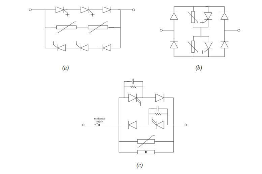
Figure 3: a) IGCT based medium voltage bi-directional solid-state circuit breaker, (b) IGCT based medium voltage bi-directional solid-state circuit breaker, (c) GTO based bidirectional solid-state circuit breaker
A simplified block diagram of a solid-state circuit breaker is shown in Figure 4. The solid-state current interrupter is comprised of a series string of solid-state devices to safely handle the DC bus voltage. A fast coordinated inverse-time controller provides the gate drive signal for the switches in the interrupter which synchronously open and close. The fast inverse time controller receives commands from either a manual input, from other breakers in the network, or from fast sensors that detect local fault currents. The inverse-time controller provides inverse trip time control for overcurrent states, and a fast instantaneous trip if the overcurrent limit is reached. These operational parameters can be adjusted for each breaker depending on its location in the network, providing an orderly, sequenced response to fault conditions.
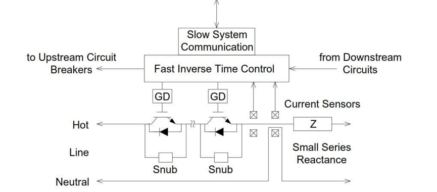
Figure 4: Simplified system diagram of a typical MVDC solid-state circuit breaker
he solid-state interrupter provides the primary functionality of a complete circuit breaker assembly fast fault protection and isolation. The complete circuit breaker assembly must also provide a means of safely disconnecting the interrupter from the power network when maintenance or service is required.
A preliminary layout for an 8 MW load-level circuit interrupter is shown in photo 1. This interrupter
consists of six 4,500 V IGBTs (CM900HB-66H) connected in series. The 8 MW interrupter is
approximately 23” wide x 9” high 11” deep and weighs approximately 60 lb. The IGBTs are mounted
on water-cooled aluminum cold plates, which are, in turn, mounted on an electrically insulating mechanical
frame. The non-metallic water lines are sufficiently resistive to limit the current leakage down the lines.
This will require a small, closed-loop cooling system and a long-lasting ion-exchange cartridge to maintain
the resistivity of the cooling water.
This will require a small, closed-loop cooling system and a long-lasting ion-exchange cartridge to maintain the resistivity of the cooling water.
In photo 1 shows the preliminary mechanical layout of a 10 kV, 8 MW (800 A) IGBT interrupter. The IGBTs are mounted on water-cooled cold plates. Non-metallic cooling lines between adjacent cold plates are designed to stand off the full switch voltage when the switch is open.
Parallel arrays of these assemblies are used to meet the overall current requirements for the load.
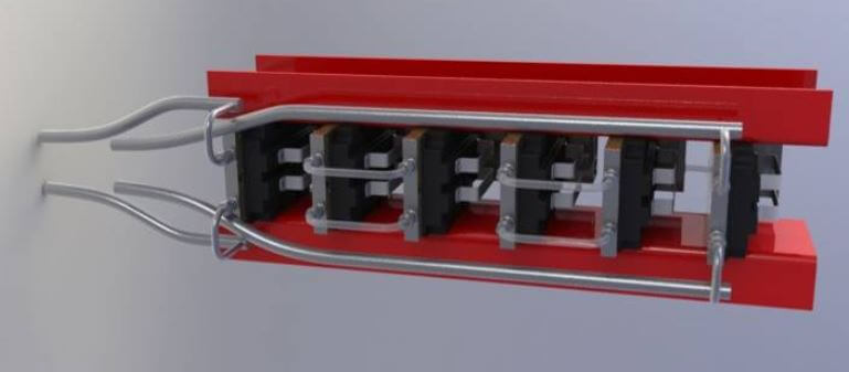
Photo 1: Preliminary mechanical layout of a 10 kV, 8 MW (800 A) IGBT interrupter. The IGBTs are mounted on water-cooled cold plates
Compare the advantages and disadvantages of Solid-State Circuit breakers with other circuit breakers briefly:
While solid-state circuit breakers can achieve substantially faster interruption speed compared to conventional electro-mechanical-based circuit breakers, one major drawback of solid-state breakers is their high on-state losses. With contact resistance as small as a few micro-ohms, electro-mechanical contacts in classical circuit breakers introduce negligible on-state losses. In contrast, most solid-state devices introduce a voltage drop of at least two volts, therefore as a large current flows through the breaker, the on-state losses of a solid-state circuit
breaker can be significantly higher than those of a classical circuit breaker. The increased energy loss also leads to increased requirements for cooling. Traditionally large metallic heatsinks are used to passively cool power semiconductor devices, however, they can contribute to substantial portions of the systems’ overall size and weight. While the installation of active cooling systems such as forced air (fan) or liquid cooling might help to reduce the size and weight of the overall system, they introduce additional complexities such as increased acoustic signature, energy losses, and maintenance issues.
According to figure 5, the values are given in relation to the highest value per group.
For every criterion, small values are considered to be preferable. A small area, therefore, indicates an overall good performance of a switching concept.
Based on the findings, the solid-state circuit-breaker shows a good overall performance. Due to its fast switching capabilities, the turn-off time is small and only low current amplitudes occur. Also, the reliability and the complexity of the switching process can be considered to be good. However, the solid-state breaker suffers from high losses, compared to mechanical or hybrid switches.
An alternative concept with low losses, medium relative costs, and good reliability is the snubber mechanical breaker. Also, the conventional hybrid breaker shows an overall medium performance. It suffers from high peak currents due to the mechanical switch. The concepts taken from HVDC systems do not have a good performance within the voltage and power levels investigated. However, for higher voltages and powers, this might change. Finally, the concept of a pure mechanical-breaker is still interesting for low and low-medium voltage applications since it’s the only well-proven one.
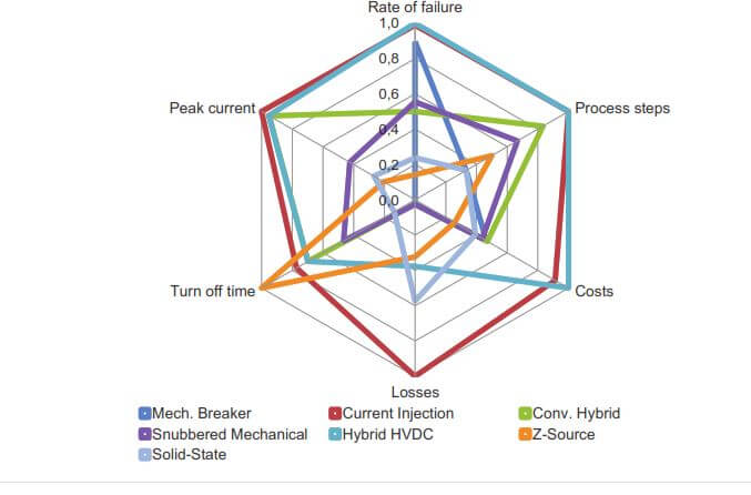
Figure 5: Overview of all switching concepts for DC circuit breakers
Table 1 summarizes the characteristics of the four circuit breaker technologies:
It should be noted that the time of preparation of this table is 2012.
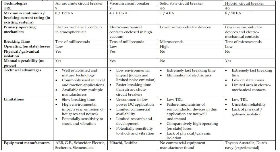
Table 1: Summary of circuit breakers technologies for low power DC applications


