What is Polarity Test of Transformer ?

Encyclopedia
08/09/2024

What is Polarity Test of Transformer ?

Polarity Test Definition

A polarity test of transformer is a method to ensure correct polarity alignment when connecting transformers in parallel.

Dot Convention

The dot convention identifies the polarity of windings in a transformer, showing how voltage is induced.

  • If a current enters the dotted terminal of one winding, then the voltage induced on the other winding will be positive at the dotted terminal of the second winding.

  • If a current leaves the dotted terminal of one winding, then the polarity of the voltage induced in the other winding will be negative at the dotted terminal of the second winding.

Additive Polarity

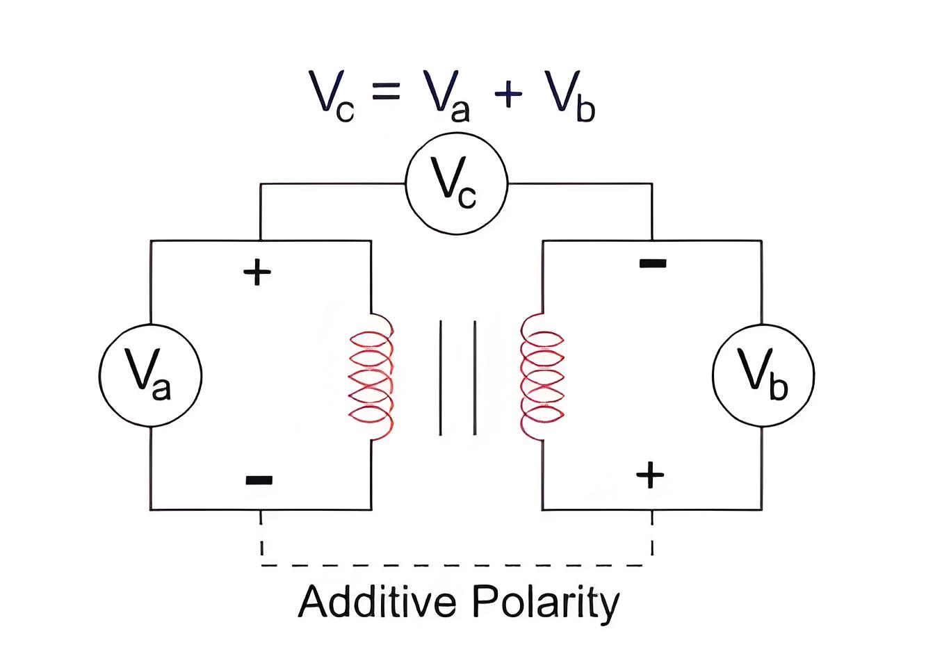
In additive polarity, the voltage between primary and secondary windings adds up, used in small transformers.
bf8a5490742bea73d6b2520ce5bb6fdb.jpeg

Subtractive Polarity

In subtractive polarity, the voltage between primary and secondary windings is the difference, used in large transformers.

Testing Procedure
2df4de911d477027c35152e7503fcf43.jpeg

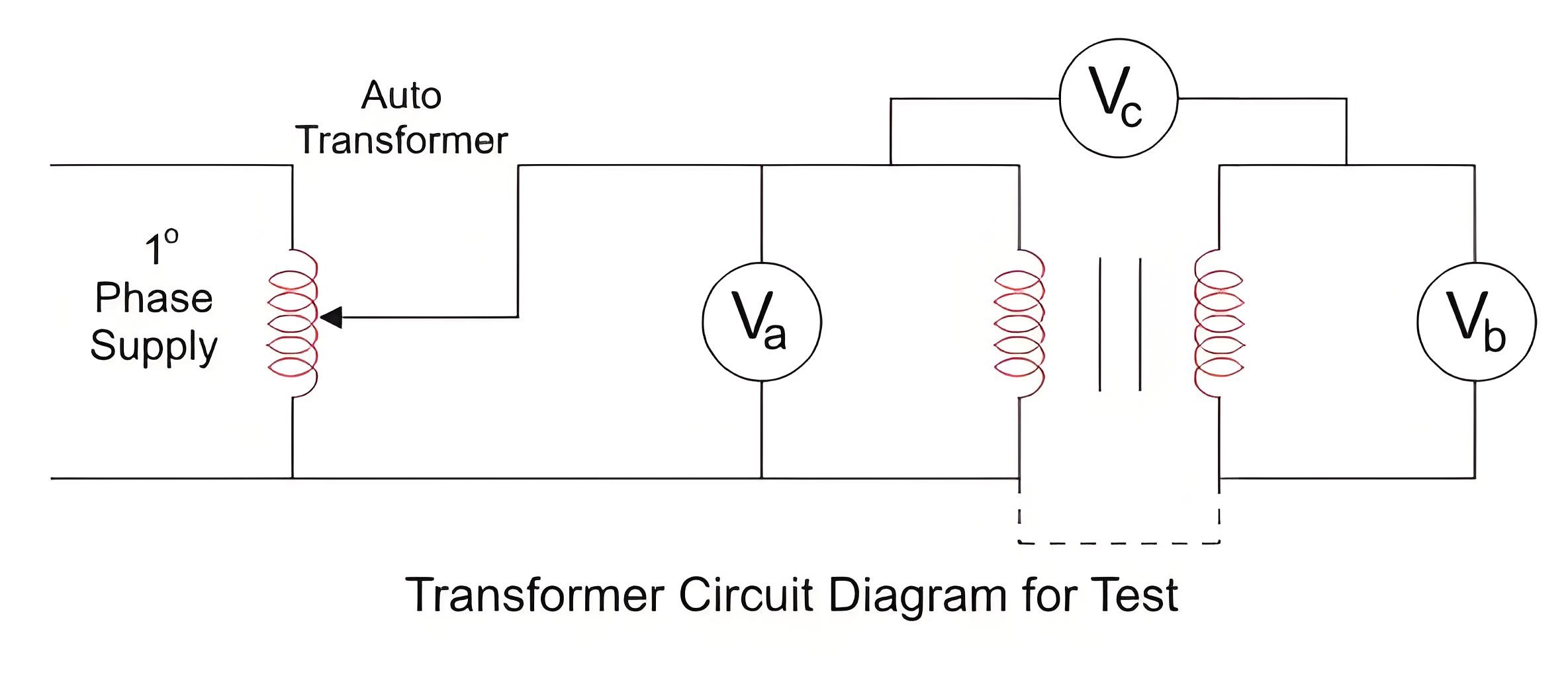
  • Connect the circuit as shown above with a voltmeter (Va) across primary winding and another voltmeter (Vb) across the secondary winding.

  • If available, take down the ratings of the transformer and the turn ratio.

  • We connect a voltmeter (Vc) between primary and secondary windings.

  • We apply some voltage to the primary side.

  • By checking the value in the voltmeter (Vc), we can find whether it is additive or subtractive polarity.

If additive polarity – Vc should be showing the sum of Va and Vb.

If subtractive polarity – Vc should be showing the difference between Va and Vb.

Caution

Be careful that the max. measuring the voltage of voltmeter Vc should be greater than the sum of Va (Primary winding) and Vb (Secondary winding) otherwise during the additive polarity, the sum of Va and Vb comes across it.

Note

If additive polarity is needed but we have subtractive, we can fix it by keeping one winding as is and reversing the other winding’s connections. The same applies if we need subtractive polarity but have additive.

Encyclopedia

The Electricity Encyclopedia is dedicated to accelerating the dissemination and application of electricity knowledge and adding impetus to the development and innovation of the electricity industry.
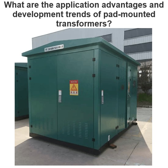
What are the application advantages and development trends of pad-mounted transformers?
In the reconstruction and expansion of modern urban power grids, to optimize the power supply layout, it is required that high - voltage directly enters urban areas, medium - voltage penetrates deep into load centers to shorten the low - voltage power supply radius, and underground cable laying is mostly adopted for urban main roads. Electrical equipment needs to meet the requirements of intelligence, miniaturization, high reliability and aesthetics. The compact substation is widely used in urba
Echo
06/17/2025
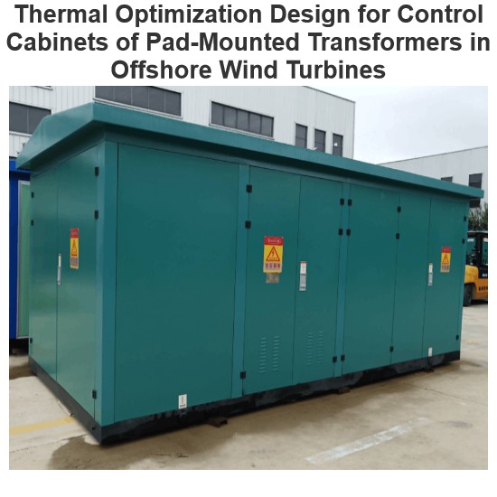
Thermal Optimization Design for Control Cabinets of Pad-Mounted Transformers in Offshore Wind Turbines
Global energy transition boosts offshore wind power, yet complex marine environments challenge turbine reliability. The heat - dissipation of pad - mounted transformer control cabinets (PMTCCs) is critical—undissipated heat causes component damage. Optimizing PMTCC heat dissipation improves turbine efficiency, but research mostly focuses on onshore wind farms, neglecting offshore ones. Thus, design PMTCCs for offshore conditions to enhance safety.1 PMTCC Heat - Dissipation Optimization1.1
Dyson
06/17/2025
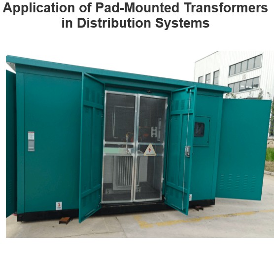
Application of Pad-Mounted Transformers in Distribution Systems
I. Design Principles of Pad-mounted TransformersWith the upgrading of power infrastructure, pad-mounted transformers are widely used in various scenarios due to their light weight, small size, low loss, low noise and high reliability. Studies show that when the power supply voltage is increased from 380V to 10kV, line loss is reduced by 60%, and copper consumption and investment are each reduced by 52%, with remarkable economic and social benefits. As a product of modern economic and social deve
Echo
06/17/2025
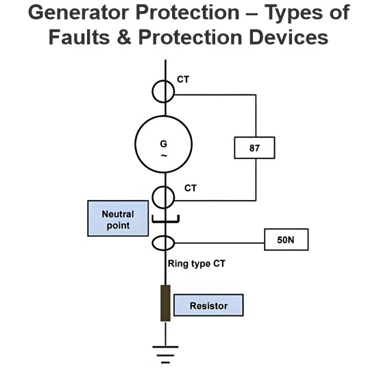
Generator Protection – Types of Faults & Protection Devices
Common Generator Faults and Protection SystemsClassification of Generator FaultsGenerator faults are primarily categorized into internal and external types:Internal Faults: Arise from issues within generator components.External Faults: Stem from abnormal operating conditions or external network issues.Faults in prime movers (e.g., diesel engines, turbines) are mechanical in nature and defined during equipment design, though they must integrate with generator protections for tripping purposes.Typ
Edwiin
06/05/2025
Inquiry
Download
Experts Electrical is dedicated to serving the personnel in the global power industry.
Join Experts Electrical, not only can you discover power equipment and power knowledge, but also canhnd like - minded friends!