What is the power angle and load in the case of a synchronous motor?
Power Angle and Load in Synchronous Motors
The power angle (Power Angle) and load in synchronous motors have a close relationship. Understanding these concepts helps to better grasp the working principle and performance of synchronous motors. Here is a detailed explanation:
1. Power Angle (Power Angle)
Definition
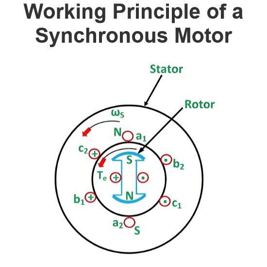
Power Angle (also known as torque angle or electric angle, denoted as δ) is the phase difference between the rotor magnetic field axis and the stator magnetic field axis. It represents the position of the rotor magnetic field relative to the stator magnetic field.
Impact
Power Transfer: The power angle directly affects the active power absorbed by the synchronous motor from the grid. The larger the power angle, the more active power the motor absorbs.
Stability: An excessively large power angle can cause the motor to lose synchronization, leading to a "slip" phenomenon.
2. Load
Definition
Load refers to the mechanical load driven by the synchronous motor, typically expressed in power units (kilowatts or horsepower).
Relationship
Power Angle and Load Relationship: The power angle δ and the load P of a synchronous motor have a nonlinear relationship, which can be expressed by the following formula:

Where:
P is the active power absorbed by the motor (watts or kilowatts).
E is the no-load EMF (electromotive force) of the motor (volts).
V is the grid voltage (volts).
Xs is the synchronous reactance of the motor (ohms).
δ is the power angle (radians).
3. Graphical Representation of Power Angle Characteristics
Characteristics Curve
Characteristics Curve: The relationship between power angle and load can be represented by a characteristic curve. This curve is typically nonlinear and follows a sine function.
Maximum Power Point: When the power angle δ reaches 90 degrees (π/2 radians), the motor absorbs the maximum active power Pmax :

Slip Point: When the power angle exceeds 90 degrees, the motor may lose synchronization, leading to a "slip" condition.
4. Influencing Factors
Grid Voltage
Voltage Variation: Changes in grid voltage V affect the relationship between the power angle and load. An increase in voltage allows the motor to absorb more active power.
Motor Parameters
Synchronous Reactance: Synchronous reactance Xs is an important internal parameter of the motor, affecting the relationship between power angle and load. A higher synchronous reactance results in less active power absorption by the motor.
Load Variation
Increase in Load: When the load increases, the motor automatically adjusts the power angle to absorb more active power until a new equilibrium point is reached.
5. Summary
Power Angle δ: Represents the phase difference between the rotor magnetic field and the stator magnetic field, directly influencing the active power absorbed by the motor.
Load P: The mechanical load driven by the motor, having a nonlinear relationship with the power angle.
Relationship Formula: P=(EV/Xs) sin(δ) describes the relationship between power angle and load.
Maximum Power Point: When the power angle δ reaches 90 degrees, the motor absorbs the maximum active power Pmax=EV/ Xs.
Slip Point: When the power angle exceeds 90 degrees, the motor may lose synchronization.
Understanding these concepts helps to better design and operate synchronous motors, ensuring their stable operation under various conditions.
The Electricity Encyclopedia is dedicated to accelerating the dissemination and application of electricity knowledge and adding impetus to the development and innovation of the electricity industry.


