Exploring the Design and Application of Photoelectric Current Transformers in GIS

Dyson
07/07/2025

1.Design and Application Example of Photoelectric Current Transformer in GIS
This article takes a 126kV GIS project as a specific example to deeply explore the design ideas and practical application of photoelectric current transformers in the GIS system. Since this GIS project was officially put into operation, the power system has remained stable, with no major failures occurring, and the operation status is relatively ideal.
1.1 Design and Application Ideas of Photoelectric Current Transformer
In the initial stage of the project, the GIS project team had intense discussions on the layout plan of the photoelectric current transformer. The core controversy focused on: whether to arrange it in the sulfur hexafluoride SF6 gas environment or in the conventional air environment.
Scheme 1: Arranged in the Sulfur Hexafluoride Gas Environment
If this scheme is adopted, the photoelectric current transformer will be in a high - pressure sulfur hexafluoride gas environment, and the electrical connection between it and the control room needs to rely on optical fibers. However, in the high - pressure environment of sulfur hexafluoride, it is rather difficult to introduce optical fibers into the control box. If optical fibers are to be made into terminal ports similar to the form of cables, professional seamless welding technology must be adopted; but the welding process will not only interfere with the transmission of optical signals, but also the conductive path formed by welding may affect the electrical insulation performance of the current transformer, with many unfavorable factors.
Scheme 2: Arranged in the Air Environment
This scheme does not need to consider the impact of high pressure, so there are no concerns related to welding. However, it is necessary to focus on how to ensure the tightness of the current transformer, as well as the impact of eddy currents on the measurement accuracy and other potential impacts that may occur.
After rigorous analysis and comparison, the GIS project team finally selected Scheme 2. This scheme takes the safety, reliability and stability of system operation as the primary consideration, and fully takes into account the operability during the implementation of the scheme.
2. Solution to Scheme Problems
Structural Design and Connection
By comparing and analyzing the design structure of the photoelectric current transformer with that of the traditional electromagnetic current transformer, it is determined to arrange the photoelectric current transformer in the air environment, and carry out the following design work:
Produce an adapted large - scale flange, place the photoelectric current transformer inside the flange, and lead out the optical fiber from the side of the flange. In this way, the connection part between the optical fiber and the photoelectric current transformer is located inside the transformer, and this area is adjacent to the large flanges of other external transformers, and the photoelectric current transformer and the sulfur hexafluoride gas are isolated by metal.
Since eddy currents will be generated during the operation of the current transformer, which will interfere with the measurement accuracy and voltage of the photoelectric current transformer. To solve this problem, electrostatic spraying treatment is adopted on the metal contact surfaces of the two large flanges, so as to block the eddy current loop and ensure the tightness of the sulfur hexafluoride gas.
Electric Field Simulation and Verification
Due to the adoption of the flange structure in the design, the electric field distribution of the photoelectric current transformer will change. To verify the effectiveness of the scheme, it is necessary to use mature simulation calculation tools (such as ANSYS software) to carry out testing and analysis work. Use ANSYS to conduct field strength experiments on the metal rings and conductors of the two flanges. The lightning impulse voltage used in the experiment is 150kV. Through precise analysis by ANSYS software, it is concluded that the field strength at the edge parts of the flange and the shielding cover is the largest, and the maximum value reaches 20kV/mm. This result has passed the test and acceptance after in - depth research and scientific and precise simulation calculations by the project team.
At present, this project has been running stably for a long time, and the effect is good. Currently, certain achievements have been made in the research of photoelectric current transformers in China. However, in the application scenarios of high voltage levels, there are still problems such as reducing the influence of birefringence caused by stress and temperature, ensuring the long - term stable operation of the system, and further improving the measurement accuracy, which need to be solved in the follow - up.
3. Conclusion
Through the discussion of the whole process from scheme selection, implementation to problem solving of the photoelectric current transformer in the GIS system, it can be seen that remarkable results have been achieved in the field of GIS design and application. Compared with the traditional electromagnetic current transformer, the photoelectric current transformer has obvious advantages, and its application range is becoming wider and wider. Many manufacturers and users have already adopted it. It is foreseeable that in the near future, the photoelectric current transformer is expected to completely replace the electromagnetic current transformer, and with the continuous development and maturity of technology, it will make greater contributions to the progress of transformer technology.
Dyson

Focused on the design of electrical equipment, proficient in electrical principles and relevant specifications, and skilled in using design software. From intelligent substations to various types of electrical equipment, I am adept at optimizing design solutions, integrating new technologies. With practical experience and collaborative management capabilities, I deliver outstanding electrical design achievements.

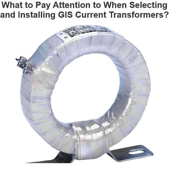
What to Pay Attention to When Selecting and Installing GIS Current Transformers?
Hi everyone, I'm James, and I've been working with current transformers (CTs) for 10 years. Today, I’ll talk about what you need to watch out for when selecting and installing GIS current transformers.Part 1: Key Considerations During Selection1. Accuracy ClassProtection-grade CTs: Used for relay protection — focus on overload capacity and transient response.Metering-grade CTs: Used for billing purposes — require high accuracy, usually 0.2S or 0.5S class.2. Rated Primary Curren
James
07/07/2025
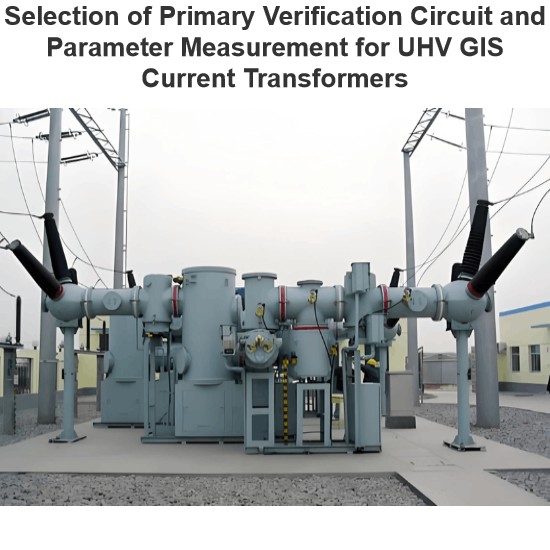
Selection of Primary Verification Circuit and Parameter Measurement for UHV GIS Current Transformers
In UHV GIS, current transformers are key to electric energy metering. Their accuracy determines power trade settlements, so on - site error verification perJJG1021 - 2007is needed. On - site, use power supplies, voltage regulators, and current boosters. Due to encapsulation in GIS, build test circuits via exposed grounding knives, bushings, and return conductors; right circuits simplify wiring and boost accuracy.Challenges like large test current, long circuits, and high impedance exist, but rea
Oliver Watts
07/07/2025
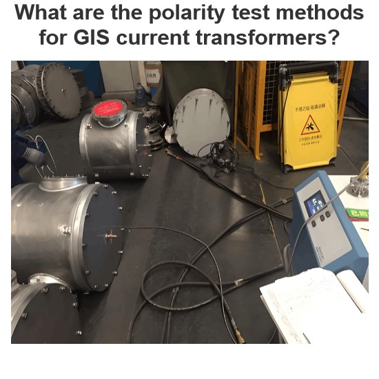
What are the polarity test methods for GIS current transformers?
I’m Oliver, an 8 - year current transformer testing pro. Today, let’s break down new and old polarity test methods for GIS current transformers—how they work and their pros/cons.1.Testing Methods1.1New MethodPre - test ops: Open FDS21/FDS22 fast disconnectors + DS23 disconnector. Close CB21 breaker, then ES21/ES22 grounding disconnectors. Disconnect ES21’s SF6 - shell ground.Wiring: Connect battery between ES21’s moving contact (negative grounded) + ground electrode
Oliver Watts
07/07/2025
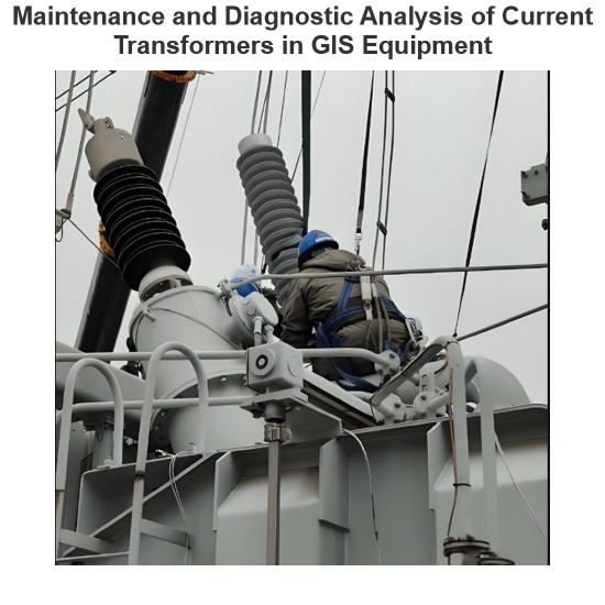
Maintenance and Diagnostic Analysis of Current Transformers in GIS Equipment
I'm Oliver, with 8 years of experience in current transformer testing. These are all practical experiences, shared with you1 Maintenance of Current TransformersHaving been in the business of current transformer testing for 8 years, I know a thing or two about their maintenance! The maintenance of current transformers is divided into minor repairs, intermediate repairs, and major overhauls.Minor repairs mainly involve opening the cover (if necessary) and changing the oil, usually carried out once
Oliver Watts
07/07/2025
Inquiry
Download
Experts Electrical is dedicated to serving the personnel in the global power industry.
Join Experts Electrical, not only can you discover power equipment and power knowledge, but also canhnd like - minded friends!