As a technician deeply involved in charging pile testing on the frontline, my daily work makes one thing crystal clear: as people’s living standards rise, the demand for vehicles surges. Coupled with the growing popularity of environmental protection concepts, the electric vehicle (EV) industry is booming. Charging piles, as the “lifeline” of electric vehicles, directly determine whether EVs can operate stably and safely. Put simply, our job in testing is to “diagnose” charging piles, ensuring their performance is rock - solid. This work demands meticulousness and precision.
1. Overview of Electric Vehicle Charging Piles: Industry Development and Significance of Testing
The global manufacturing industry is in high gear, consuming resources at an astonishing rate. Critical resources like petroleum are fiercely competed for across various sectors, and reserves are dwindling rapidly. As a derivative of petroleum, the demand for gasoline and diesel has skyrocketed along with the increasing number of vehicles. From an environmental and sustainable development perspective, fuel - powered vehicles are destined to be phased out. Currently, hybrid and pure electric vehicles are gaining popularity due to their low or zero fuel consumption, and the charging equipment industry is “taking off” in tandem, with new technologies and devices emerging constantly.
From a testing perspective, there are several key classifications for charging equipment:
- By Electrical Input: AC charging piles (relying on the on - board charger for power conversion) and DC chargers (directly supplying power to the battery);
- By Installation Method: Floor - mounted and wall - mounted, selected based on site conditions;
- By Equipment Structure: Split - type and integrated, affecting installation and maintenance difficulty;
- By Accuracy Level: Class 1 and Class 2, determining the precision of energy measurement. These classifications form the “baseline knowledge” I must master before each test.
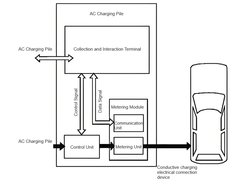
AC charging piles act as “intermediaries” supplying AC power to the on - board charging system: single - phase piles are suitable for small vehicles, typically taking 3–8 hours to fully charge; three - phase piles enable fast charging for medium - to - large buses, reaching 80% charge in half an hour. Through years of testing, I’ve come to realize that charging pile testing must be “comprehensive” — parameters such as output voltage, current, and frequency directly reflect the pile’s control, data acquisition, and processing capabilities. Moreover, the safety of charging piles is “a matter of life and death”; any malfunction can render an EV inoperable.
However, current testing methods have limitations. The environmental testing method, which uses physical batteries, fails to simulate real - world charging conditions, leading to large errors and low efficiency. This compels us frontline testers to advance alongside the R & D of new energy vehicles, improving testing standards to truly drive industry progress.
2. On - Site Testing Methods for Electric Vehicle Charging Piles: Practical Insights from the Frontline
2.1 Configuration of the On - Site Testing Platform
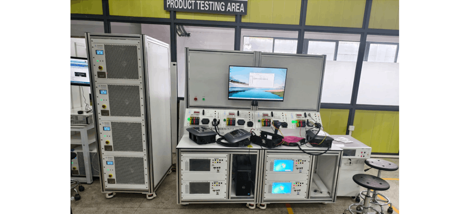
2.1.1 Hardware Platform
The automatic testing platform we use must be compatible with AC pile testing and support interoperability. For example, when testing a three - phase 63A pile, the AC power supply is set to 60kVA, outputting 0VAC–300VAC to minimize harmonic current and avoid grid interference. Single - phase independent loading, with each phase operating separately, simulates the loading conditions of nonlinear charging modules and chargers, generating an impact force twice the rated current. These parameter settings are “battle - tested” insights gained from countless tests.
Charging piles rely on AC power supplies and must simulate “disruptions” like harmonics and voltage sags in the mains supply, ensuring the pile’s data meets national standards under extreme conditions. Pure resistive loads are programmed for single - phase control, meeting testing requirements for both single - phase and three - phase piles.
Using the AC charging test interface to simulate ground faults and switch logic, combined with power supplies and loads, we can understand the compatibility between the pile and the EV, verifying the effectiveness of protective actions. High - precision power meters collect voltage and current data; a 6.5 - digit digital multimeter is installed in the data acquisition card with 20 channels for simultaneous measurement. Signal gating devices work with oscilloscopes to capture switching signals, and serial servers connect to industrial computers for real - time data exchange and reporting. This hardware setup is the “backbone” of testing accuracy.
2.1.2 Testing Software
The software must be open, integrating various test data to centrally manage devices, programs, and reports while ensuring data security. The software I commonly use features a secondary programming interface, facilitating frontline testers to adjust programs and process data.
The human - machine interface (HMI) is highly functional: parameter detection, dynamic display, operation control, and report generation, with online customization of interface effects. The client module communicates via data interfaces and control commands; the control command module receives, executes, and verifies commands, unifiedly managing device interfaces. If hardware changes, configurations are updated to simplify upgrades. The data module is responsible for data collection, storage, and processing, separating parameter and result verification, and defining hardware configurations.
I’m well - versed in the software operation process: log in, select test items, adjust program commands in real - time, and send instructions to the control cabinet. After executing a project, view edit commands on the left and variables/reports on the right. Online monitoring allows adjustment of oscilloscopes and power analyzers; start testing, collect data, and save to a folder. This streamlined process significantly boosts testing efficiency.
2.2 Testing Items: Key Checkpoints for Frontline Testing
2.2.1 Inspection of Appearance and Structure
During each test, my first step is to check the charging pile’s casing and nameplate. The nameplate must be clear and complete, with proper safety protections in place, and free from rust or dust. “Hidden aspects” like the power supply, operating environment, electric shock protection, and electrical clearance must strictly comply with standards. The pile body must be clean, free of cracks and burrs, and have neatly arranged wiring. An emergency stop button is mandatory, allowing for immediate power cutoff in case of faults. The pile body must be durable, resistant to corrosion and high temperatures, and its internal components must be protected against water and rust. Overlooking any of these details could pose potential hazards.
2.2.2 Inspection of Indicators and Displays
Though small, indicators and displays are crucial! Verify their status during charging, faults, and operation: indicators should light up or flash during operation, remain steadily lit during normal power - on, stay lit (operation indicator) with the charging indicator turning off during charging, and show a steady operation indicator with a flashing fault indicator during overvoltage/overcurrent. They must also display real - time battery info, charging duration, voltage, and current, with fault warnings and manual records. Malfunctions in these functions leave drivers unable to assess the pile’s status.
2.2.3 Functional Testing
During automatic or manual testing, BMS data must be used to adjust charging parameters, ensuring charging quality. Before manual operation, parameters are set, devices installed, and output voltage/current limits monitored in real - time. If the voltage exceeds limits during constant current operation, switch to constant voltage; if the current exceeds limits during constant voltage operation, limit the current; in case of abnormal AC voltage, shut down immediately. These logics are “hard rules” for ensuring charging safety.
2.2.4 Measurement Function Testing
Measurement is the “heart” of charging piles, involving tests for operation error, indication error, payment error, and clock error. When the load current is between maximum and minimum, Class 1 piles must have an error ≤±1%, Class 2 ≤±2%; payment amounts must align with unit price and energy consumption; clock error must not exceed 5 seconds for the first test, with a 3 - minute testing duration. These precision requirements directly impact user costs and charging experience.
3. Application Examples of On - Site Testing for Electric Vehicle Charging Piles: Frontline Battle Records
3.1 Actual Pile and Load Testing
3.1.1 Testing Object
To validate testing methods, I selected a DC pile at a charging station, focusing on its load performance — frontline testing demands “real - world verification” to truly understand performance.
3.1.2 Testing Conclusions
Taking Pile No. 1 as an example, tests revealed:
- When output voltage deviated, the constant current was 60A;
- When output current deviated, the constant voltage was 400V;
- The voltage - time graph met circuit control requirements.
This test combined AC and DC side measurements, enabling the charger to operate under load, maintaining constant voltage stability. With an input voltage of 500V, load current was optimized, and power was measured in real - time — this comprehensive approach thoroughly assessed the pile’s performance.
3.2 Testing Issues and Improvements: Frontline Challenges and Solutions
- Equipment Issues: Testing devices can display communication messages but fail to generate standardized protocol consistency reports, reducing efficiency; difficulty in achieving constant voltage/current; low integration and portability, with bulky resistive loads.
Solution: My team and I added protocol consistency reporting to devices, introduced constant voltage/current modes, and pushed for device integration — frontline testers must proactively solve these “bottlenecks”.
-
Protocol Update Issues: Some piles update communication protocols to international standards, making testing with old standards inaccurate. Testing platforms must support both old and new standards — we must keep pace with industry updates.
-
Inadequate Testing Content: Wireless communication interference during human - machine/network interaction disrupts the EV - to - network APP connection; manual restarts resolve pile faults, requiring core product fault analysis.
Solution: Testing platforms must include these scenarios, evaluating wireless communication stability and fault self - recovery — frontline issues must be exposed and resolved during testing.
4. Conclusion: A Frontline Tester’s Aspirations for the Industry
Electric vehicles rely on charging piles for “energy”. To ensure charging piles are reliable and durable, efficient supervision and inspection systems are essential. As frontline testers, we work closely with piles daily, hoping to identify performance and safety issues through real - time testing and implement practical solutions, ensuring the new energy vehicle industry thrives. Industry progress hinges on solid work, and we testers must “hold the line” in this critical link.