Electrical Transmission Tower Earthing
Earthing Definition
Earthing of electrical transmission towers is defined as a safety measure where each tower is grounded to prevent electrical hazards.
Footing Resistance
Measuring the footing resistance ensures it is below 10 ohms, crucial for tower safety.
Pipe Earthing
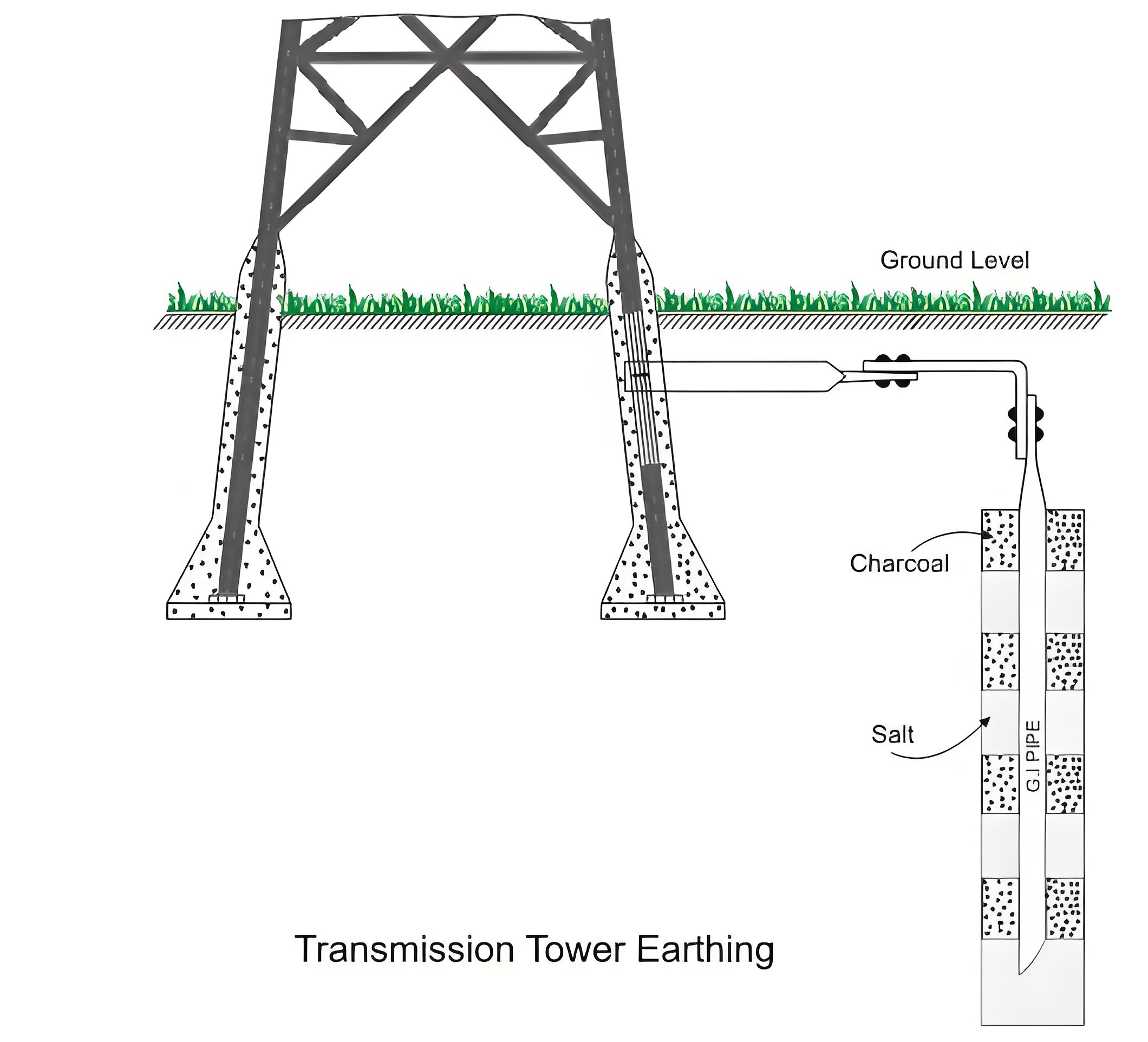
In the pipe earthing system, we use a galvanized steel pipe that is 25 mm in diameter and 3 meters long. The pipe is buried vertically in the soil, with its top 1 meter below ground level. If the tower stands on rock, the earthing pipe must be buried in damp soil near the tower.
The tower leg is then connected to the pipe using galvanized steel tape of an appropriate cross-section. The steel tape must be buried in a groove cut into the rock and protected from damage.
In case of pipe earthing system we fill surroundings of the pipe with alternating layers of charcoal and salt, which maintain the surrounding soil of the pipe moist. A details pictorial representation of a pipe earthing is down here below.
Counterpoise Earthing
We use 10.97 mm dia galvanized wire for the purpose of counterpoise earthing of electrical transmission tower. Here we connect the galvanized wire with the leg of the tower with the help of galvanized lug and the galvanized lug is fitted with a tower leg with the help of 16 mm dia nut and bolts. The steel wire used for the purpose must be of minimum 25 meters in length. The wire is buried tangentially under the ground of minimum 1 meter depth from the ground level. Here four legs of a tower are connected together with counterpoise earth wire burried below the ground level of 1 meter depth as already been told.
Tower Earthing Lug
The earthing lug extends beyond the tower’s concrete base, ensuring a proper connection.
The Electricity Encyclopedia is dedicated to accelerating the dissemination and application of electricity knowledge and adding impetus to the development and innovation of the electricity industry.

