Measurement of Reactance of a Shunt Reactor
Shunt Reactor Definition
A shunt reactor is defined as an electrical device that absorbs reactive power in power systems.
Reactance Calculation
The reactance of a shunt reactor can be calculated as it is nearly equal to its impedance.
V-I Characteristics
The simple formula of impedance in ohm is
Where, V is voltage in volt and I is current in ampere.

But in the case of shunt reactor, impedance Z = reactance X.Where, V is applied voltage across the winding of the reactor and I is the corresponding current through it.
As the V-I characteristic of the reactor is linear, reactance of the reactor winding remains fixed for any applied voltage below the maximum rated value.
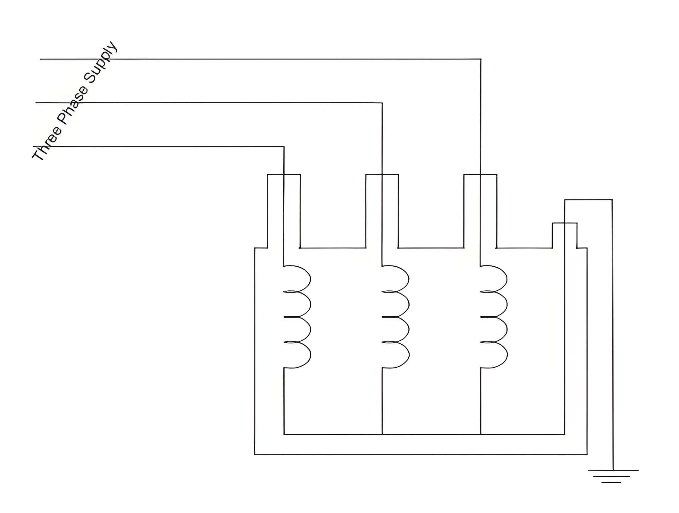
In the case of reactance measurement of three phase shunt reactor, we use sinusoidal three phase supply voltage of power frequency (50 Hz) as test voltage. We connect three supply phases to three terminals of the reactor winding as shown. Before that we should make sure that the neutral terminal of the winding is properly earthed.

Three-Phase Measurement
But in the case of shunt reactor, impedance Z = reactance X.
Where, V is applied voltage across the winding of the reactor and I is the corresponding current through it.
As the V-I characteristic of the reactor is linear, reactance of the reactor winding remains fixed for any applied voltage below the maximum rated value.
In the case of reactance measurement of three phase shunt reactor, we use sinusoidal three phase supply voltage of power frequency (50 Hz) as test voltage. We connect three supply phases to three terminals of the reactor winding as shown. Before that we should make sure that the neutral terminal of the winding is properly earthed.

Zero Sequence Reactance
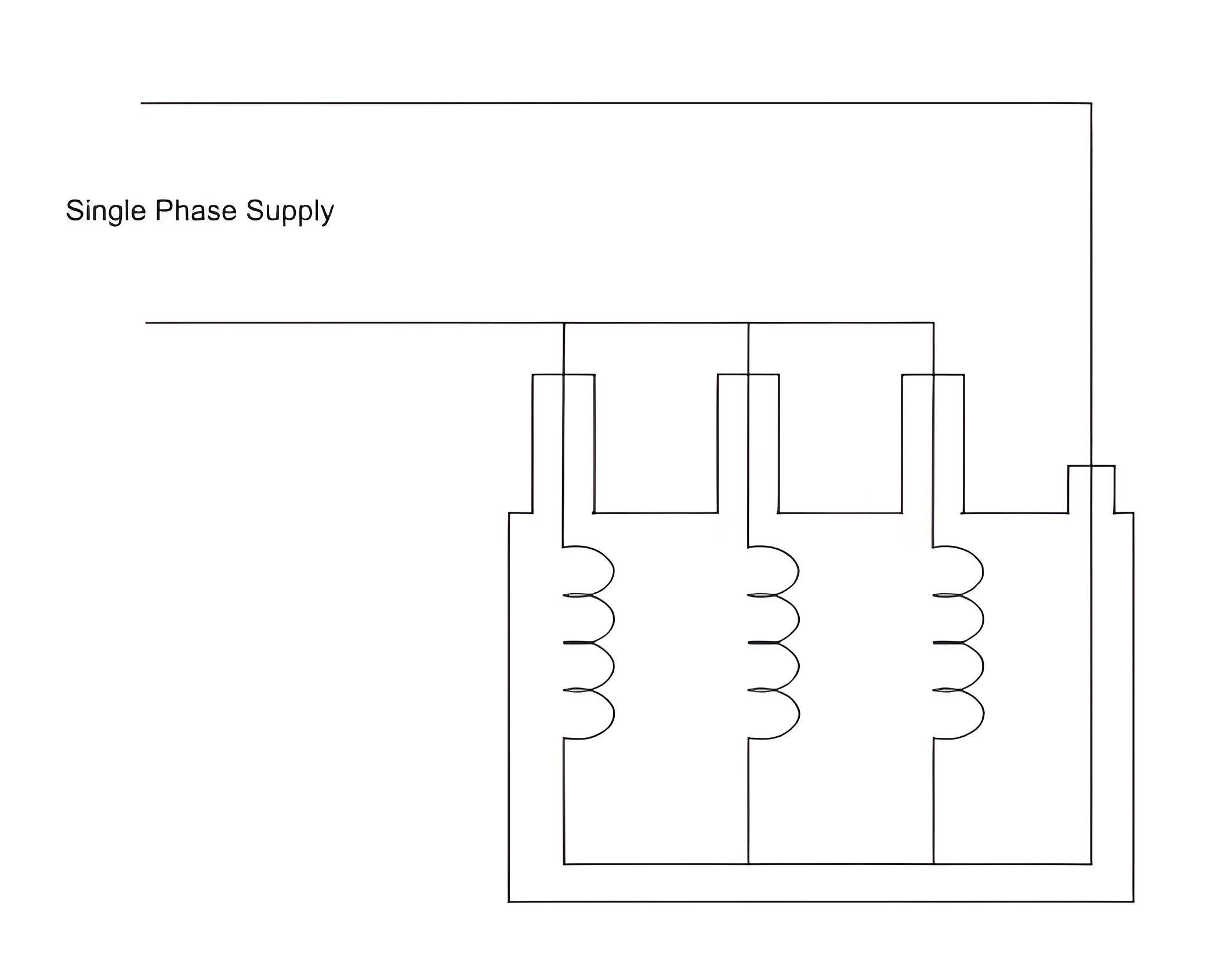
For three phase reactors with magnetic iron path for zero sequence flux, zero sequence reactance may be measured as follows.
In this method, short the three terminals of the reactor and apply a single-phase supply between the common phase terminal and the neutral terminal. Measure the current through the common path, then divide the applied single-phase voltage by this current. Multiply the result by three to obtain the zero sequence reactance per phase.
The Electricity Encyclopedia is dedicated to accelerating the dissemination and application of electricity knowledge and adding impetus to the development and innovation of the electricity industry.
