What is Transmission Tower Foundation?
What is Transmission Tower Foundation?
Transmission Tower Foundation Definition
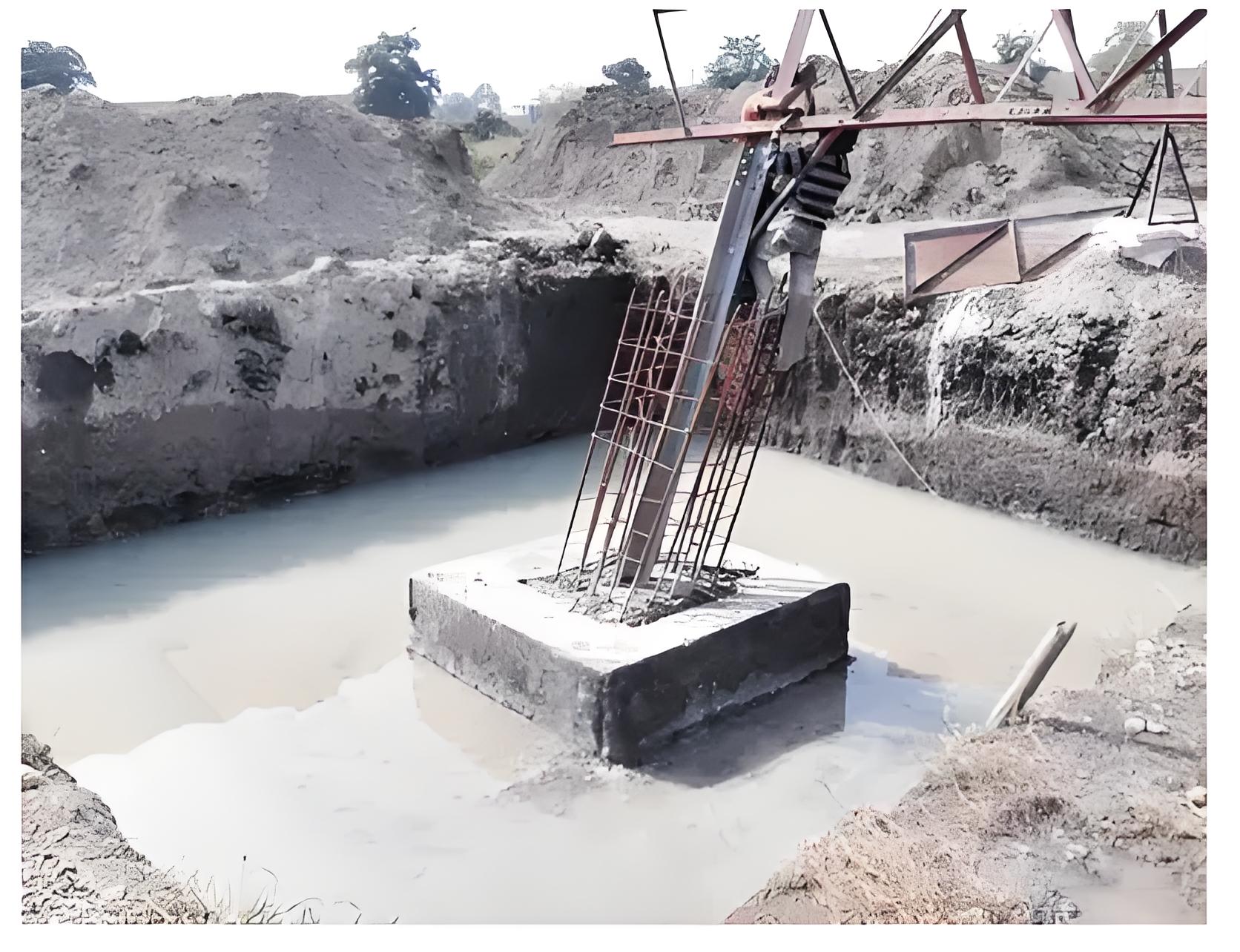
A transmission tower foundation is defined as the base that supports the tower and transfers loads to the ground.
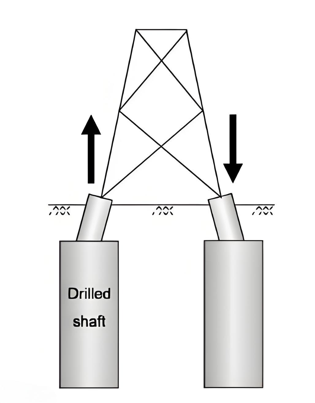
Types of Loads
The foundation of towers are normally subjected to three types of forces. These are:
The compression or downward thrust.
The tension or uplift.
The lateral forces of side thrusts in both transverse and longitudinal directions.
The magnitude or limit loads for foundations should be taken 10% higher than these for the corresponding towers.
The base slab of the foundation should be designed to handle extra forces caused by uneven load distribution.
The weight of concrete both above and below ground level, along with any embedded steel, should be considered to add to the down-thrust.
Soil Parameters
Soil parameters For designing the foundations, following parameters are required.
Limit bearing capacity of soil.
Density of soil.
Angle of earth frustum.
The above values are available from soil test report.
Stability Analysis
Besides strength design, stability analysis must be conducted to prevent failures like overturning, uprooting, sliding, and tilting. Soil resistance is key to counteracting the loads on the foundation.
Resistance Against Uplift
The uplift loads shall be assumed to be resisted by the weight of earth in an inverted frustum of a pyramid of earth whose sides make an angle equal to the angle of report of the earth with the vertical in average soil. The volume of earth computation shall be as per enclosed drawing (Fig.3) The weight of concrete embedded in earth and that above the ground level shall also be considered for resisting the uplift. In case where the frustum of earth pyramid of two adjoining legs overlaps each other, the earth frustum shall be assumed truncated by a vertical plane passing through the center line of the tower base. Over load factor (OLF) of 10% (Ten percent) shall be considered over the design load i.e. OLF = 1.10 for suspension tower and 1.15 for angle including dead end and anchor tower. However, for special tower OLF shall be 1.20.
Resistance Against Down Thrust of Transmission Tower Foundation
The following load combinations shall be resisted by the bearing strength of the soil:
The down thrust loads combined with an additional weight of concrete above earth are assumed to be acting on the total area of the bottom of the footing.The moment due to side thrust forces at the bottom of the footing.
The structural design of the base slab shall be developed for the above load combination. In case of toe (τ) pressure calculation due to above load combination allowable bearing pressure to be increased by 25%.
Resistance Against Side Thrust of Transmission Tower Foundation
The chimney shall be designed as per limit state method for the combined action of axial forces, tension and compression and the associated maximum bending moment. In these calculations, the tensile strength of concrete shall be ignored.
Resistance Against Uprooting of Stub of Transmission Tower Foundation
OLF of 10% (Ten percent) shall be considered i.e. OLF = 1.10 for normal suspension towers and 1.15 for angle tower including Dead end/anchor tower. For special towers OLF shall be 1.20.
The Electricity Encyclopedia is dedicated to accelerating the dissemination and application of electricity knowledge and adding impetus to the development and innovation of the electricity industry.
