What is Conductor Resistance Test?
What is Conductor Resistance Test?
Conductor Resistance Test Definition
The conductor resistance test measures the DC resistance of copper or aluminum conductors to determine how easily they allow current flow.
Importance of Resistance
Higher resistance in a conductor results in less current flow, which is crucial for efficient power transmission.
Test Equipment
The test uses a Kelvin Double Bridge or Wheatstone Bridge to measure resistance accurately.
Testing Procedure
Connect the specimen to the resistance measuring bridge and make sure that proper considerations are taken into account about the contact resistance.
Measure the resistance and note down the temperature.
Measured resistance is converted to the standard temperature and length.
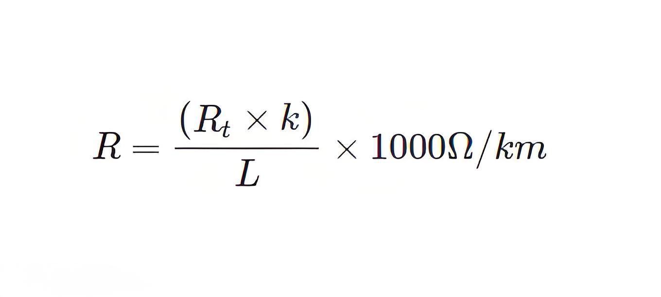
Calculation
Observed Resistance at a particular temperature,

R t = Observed Resistance
K = Temperature correction factor
L = Length of specimen in m.
Conclusion
The test results indicate if the conductor meets specified resistance standards, ensuring reliability in electrical power cables.
The Electricity Encyclopedia is dedicated to accelerating the dissemination and application of electricity knowledge and adding impetus to the development and innovation of the electricity industry.


