Transient Stability in Power System

Encyclopedia
09/04/2024

Transient Stability Definition


Transient stability is the power system’s ability to return to a stable state after significant disturbances like faults or sudden changes in load.


Swing Equation


The swing equation helps determine how changes in load affect a generator’s stability by analyzing the dynamics between mechanical and electromagnetic forces.


099474db64b5dea52e72f6e4a6972aed.jpeg


Here for the sake of understanding, we consider the case where a synchronous generator is suddenly applied with an increased amount of electromagnetic load, which leads to instability by making PE less than PS as the rotor undergoes deceleration. Now the increased amount of the accelerating power required to bring the machine back to a stable condition is given by,


6623c80fcf708311afc052687ca8d8b4.jpeg


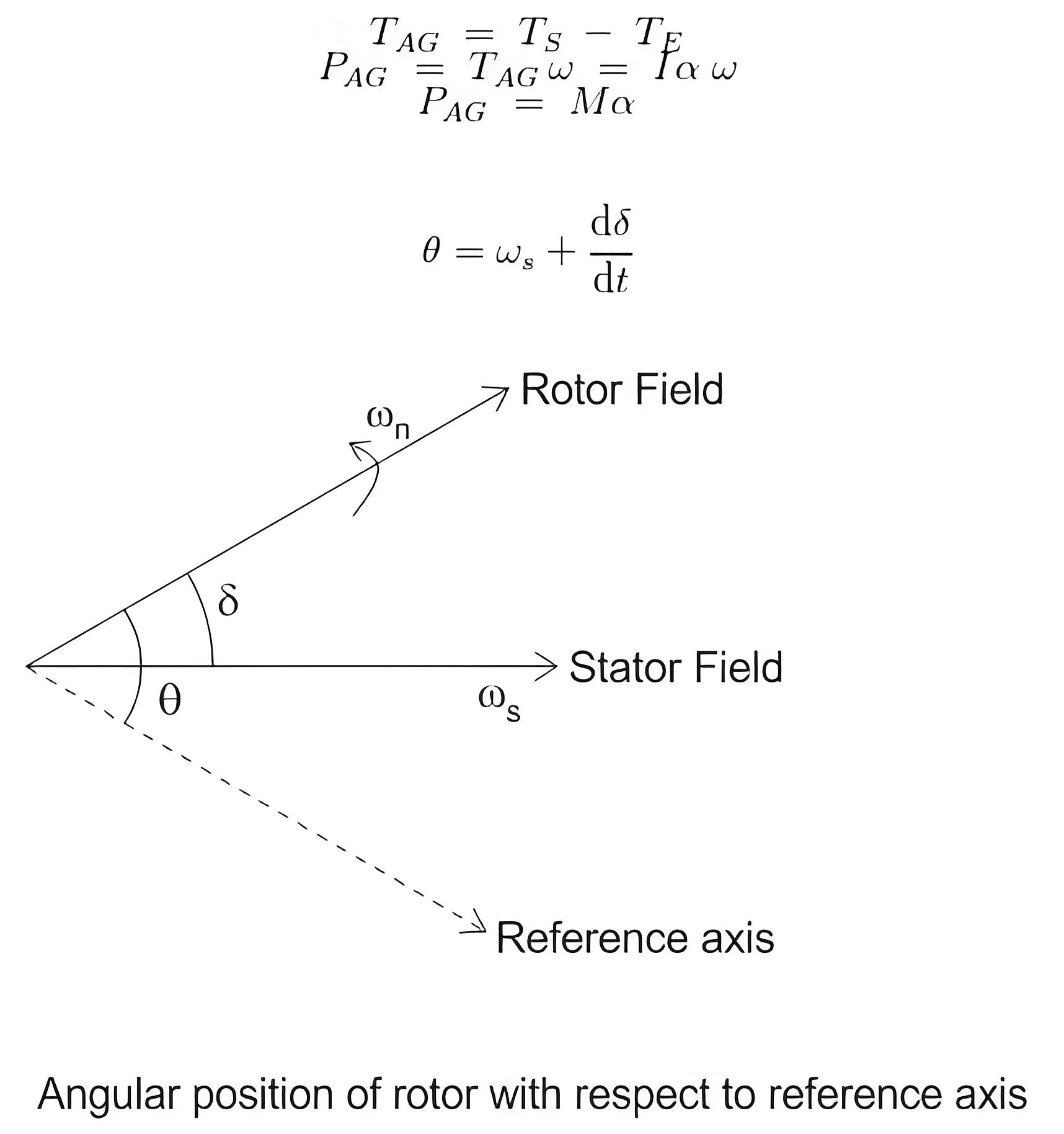
The formula for the accelerating torque is as follows:


Now we know that(since T = current × angular acceleration)Furthermore, angular momentum, M = Iω


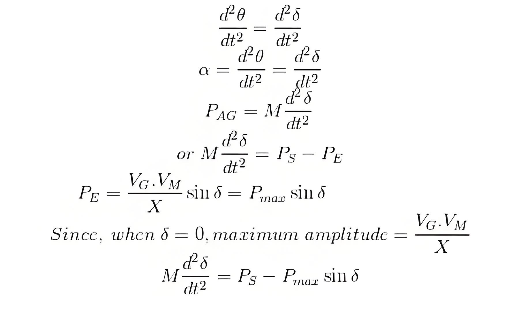
But since on loading the angular displacement θ varies continuously with time, as shown in the figure below, we can write. This is known as the swing equation for transient stability in power system.


9c48d1dd67bdb3ed9b0363e07f926ce0.jpeg


Importance of Stability


Maintaining transient stability is crucial for preventing system failures and ensuring reliable power delivery.


Instability Consequences


Without proper transient stability, power systems can experience failures, leading to blackouts and other reliability issues.


Stability Assessment


Initial studies focus on the system’s response to the first swing post-disturbance to predict its ability to regain and maintain stability.

7671a096d4a3d858e9ae8bc79da5db4c.jpeg


Encyclopedia

The Electricity Encyclopedia is dedicated to accelerating the dissemination and application of electricity knowledge and adding impetus to the development and innovation of the electricity industry.

Why is the Ground Wire Always Positioned Above the Overhead Power Lines?
Ground Wire in Overhead Transmission LinesThe ground wire (also called earth wire or OPGW) installed above phase lines in overhead transmission lines acts as a key protective and safety component. It provides lightning protection, ground fault defense, and helps prevent electrical system disruptions.In overhead transmission lines, positioning the ground wire above phase lines serves specific safety and performance purposes. Referred to as a "shield wire" or "static wire," this configuration has
Edwiin
06/04/2025
What is the Power Angle in a Power Transmission Line?
The power angle, denoted by δ, is the phase angle difference between two voltage levels in a power transmission line. Specifically, it represents the angular discrepancy between the sending-end voltage phasor and the receiving-end voltage (or between voltages at two bus points). In simpler terms, it quantifies the phase shift between voltage and current waveforms in the transmission line.Also referred to as the torque angle or load angle, this parameter is critical for two key reasons: it
Edwiin
06/04/2025
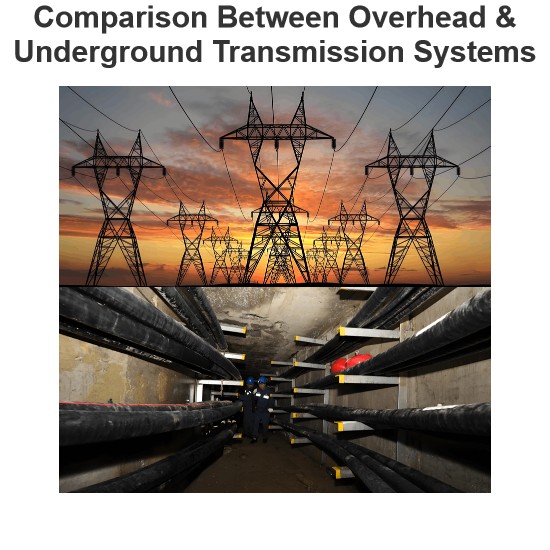
Comparison Between Overhead & Underground Transmission Systems
Key Differences and Comparison Between Underground and Overhead Power Transmission & DistributionPublic SafetyIn terms of public safety, underground systems outperform overhead transmission systems. With all transmission and distribution components buried, underground setups minimize risks from obstacles and external interference. Additionally, they are less susceptible to environmental factors like wind, storms, and heavy rain, making them inherently more secure.Initial CostUnderground syst
Edwiin
05/30/2025
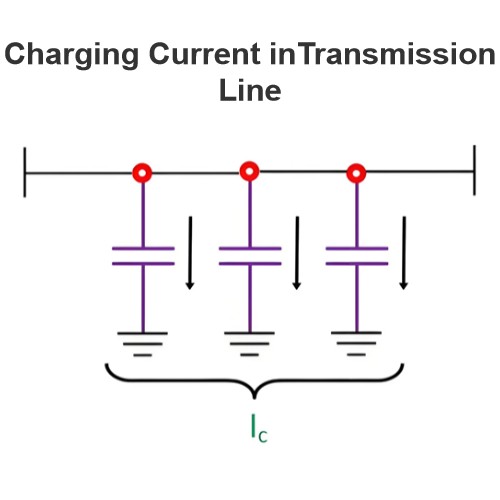
Charging Current in Transmission Line
Charging Current in Transmission LinesIn a transmission line, air serves as the dielectric medium between conductors. When voltage is applied to the sending end, current begins to flow between conductors due to the imperfect insulating properties of the dielectric. This current is known as the charging current of the transmission line.In other words, the current associated with the line capacitance is defined as the charging current. The magnitude of charging current depends on the line voltage,
Edwiin
05/23/2025
Inquiry
Download
Experts Electrical is dedicated to serving the personnel in the global power industry.
Join Experts Electrical, not only can you discover power equipment and power knowledge, but also canhnd like - minded friends!