Impedance of Transformer

Encyclopedia
09/18/2024

Leakage Reactance Definition


In a transformer, not all the flux links both the primary and secondary windings. Some flux links with only one winding, called leakage flux. This leakage flux causes self-reactance in the affected winding.


This self-reactance is also known as leakage reactance. When combined with the transformer’s resistance, it forms impedance. This impedance causes voltage drops in both the primary and secondary windings.


Resistance of Transformer


The primary and secondary windings of a electrical power transformer are usually made of copper, which is a good conductor of current but not a superconductor. Superconductors are not practically available. Therefore, these windings have some resistance, known collectively as the transformer’s resistance.


Impedance of Transformer


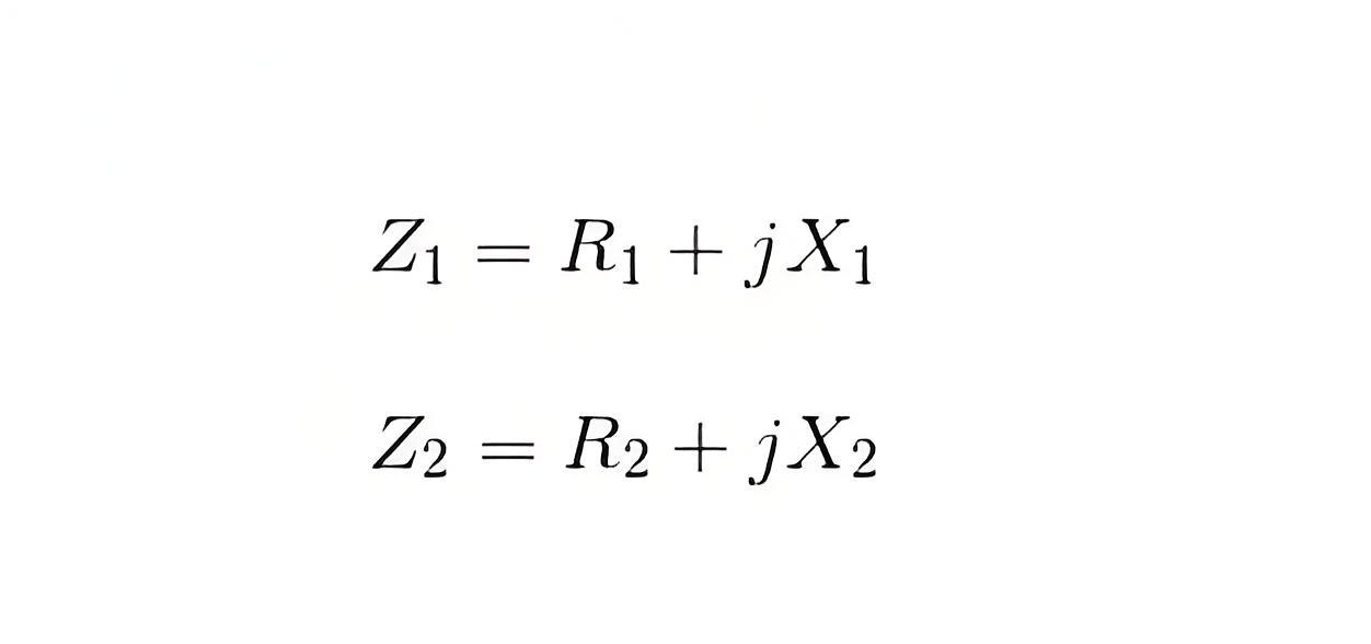
As we said, both primary and secondary windings will have resistance and leakage reactance. These resistance and reactance will be in combination, is nothing but impedance of transformer. If R1 and R2 and X1 and X2 are primary and secondary resistance and leakage reactance of transformer respectively, then Z1 and Z2 impedance of primary and secondary windings are respectively,
 

0fcb8e893e3907077dd9d360d748db34.jpeg


The Impedance of transformer plays a vital role during parallel operation of transformer


Leakage Flux in Transformer


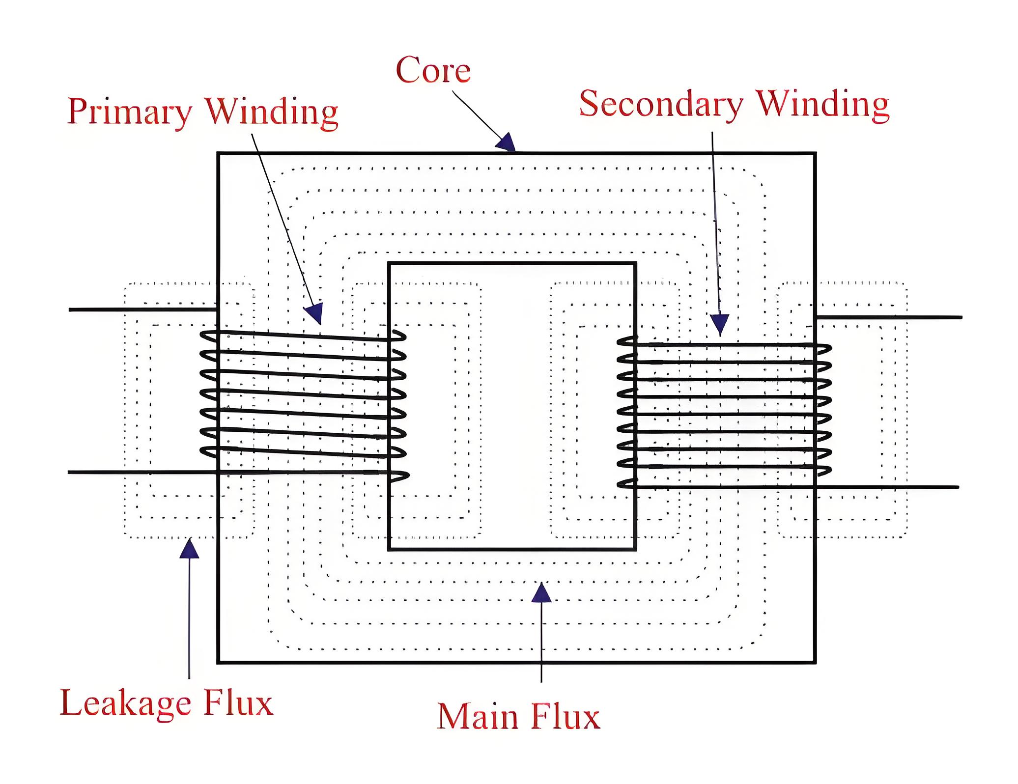
In an ideal transformer, all the flux would link both the primary and secondary windings. However, in reality, not all flux links with both windings. Most flux passes through the core of transformer, but some flux links with only one winding. This is called leakage flux, which passes through the winding insulation and transformer oil instead of the core.


Leakage flux causes leakage reactance in both primary and secondary windings, known as magnetic leakage.
 

5eca8e676844006960dabbb6691d6ae4.jpeg


Voltage drops in the windings occur due to impedance of transformer. Impedance is combination of resistance and leakage reactance of transformer. If we apply voltage V1 across primary of transformer, there will be a component I1X1 to balance primary self induced emf due to primary leakage reactance. (Here, X1 is primary leakage reactance). Now if we also consider voltage drop due to primary resistance of transformer, then voltage equation of a transformer can easily be written as,
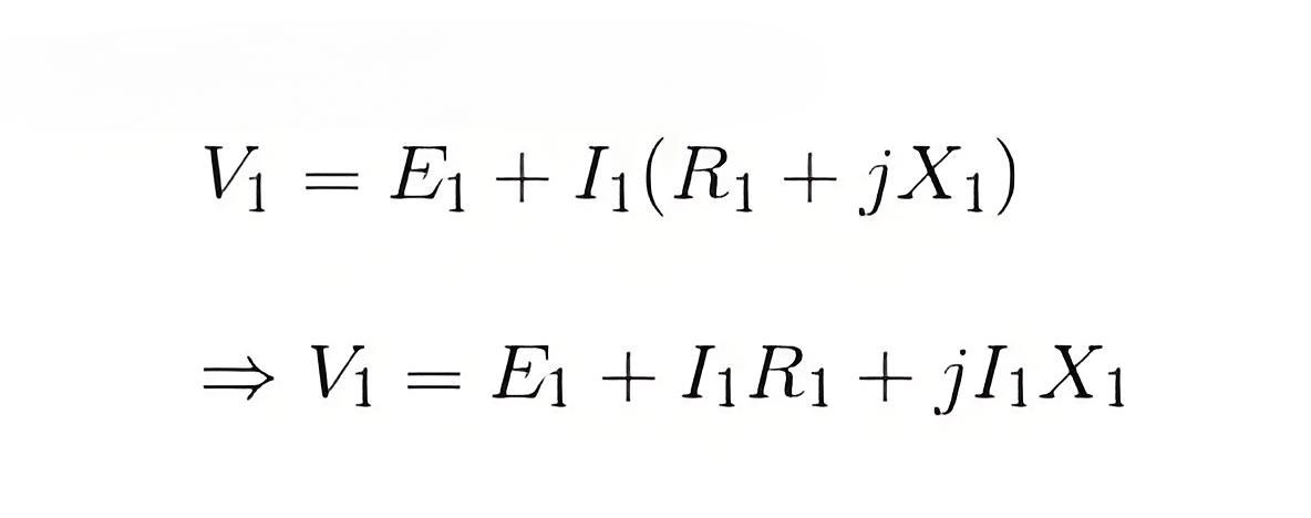
 

1b1e15812c808582b64ae2424692eb99.jpeg


Similarly for secondary leakage reactance, the voltage equation of secondary side is,
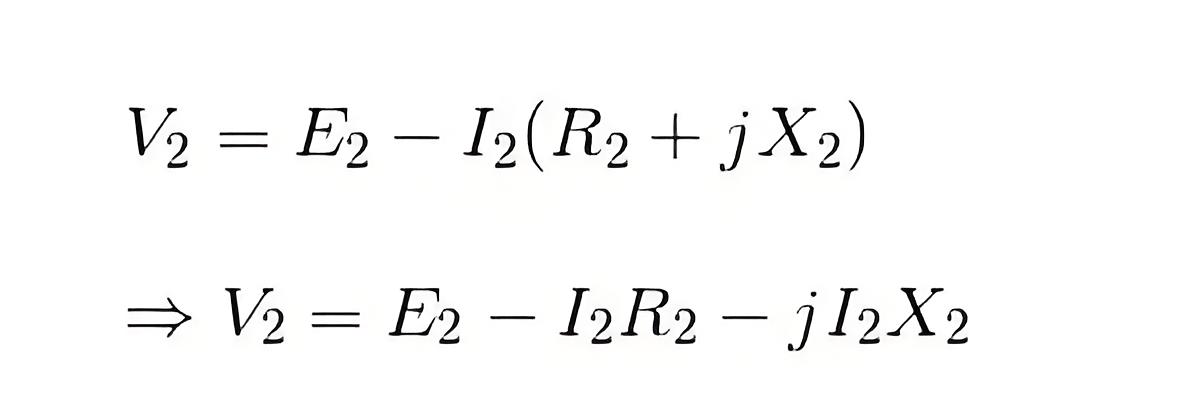
 

cf81a0116f8510e36defe66852bb6ce1.jpeg


Here in the figure above, the primary and secondary windings are shown in separate limbs, and this arrangement could result in a large leakage flux in transformer because there is a big room for leakage. 


Leakage in primary and secondary windings could be eliminated if the windings could be made to occupy the same space. This, of course, is physically impossible but, by placing secondary and primary in a concentric manner can solve the problem to a good extent. 


Encyclopedia

The Electricity Encyclopedia is dedicated to accelerating the dissemination and application of electricity knowledge and adding impetus to the development and innovation of the electricity industry.
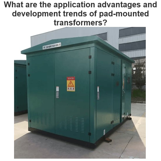
What are the application advantages and development trends of pad-mounted transformers?
In the reconstruction and expansion of modern urban power grids, to optimize the power supply layout, it is required that high - voltage directly enters urban areas, medium - voltage penetrates deep into load centers to shorten the low - voltage power supply radius, and underground cable laying is mostly adopted for urban main roads. Electrical equipment needs to meet the requirements of intelligence, miniaturization, high reliability and aesthetics. The compact substation is widely used in urba
Echo
06/17/2025
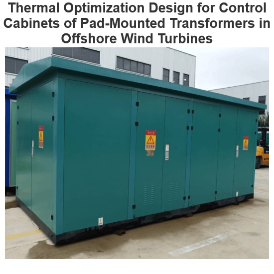
Thermal Optimization Design for Control Cabinets of Pad-Mounted Transformers in Offshore Wind Turbines
Global energy transition boosts offshore wind power, yet complex marine environments challenge turbine reliability. The heat - dissipation of pad - mounted transformer control cabinets (PMTCCs) is critical—undissipated heat causes component damage. Optimizing PMTCC heat dissipation improves turbine efficiency, but research mostly focuses on onshore wind farms, neglecting offshore ones. Thus, design PMTCCs for offshore conditions to enhance safety.1 PMTCC Heat - Dissipation Optimization1.1
Dyson
06/17/2025
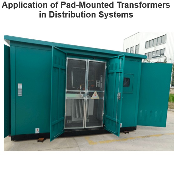
Application of Pad-Mounted Transformers in Distribution Systems
I. Design Principles of Pad-mounted TransformersWith the upgrading of power infrastructure, pad-mounted transformers are widely used in various scenarios due to their light weight, small size, low loss, low noise and high reliability. Studies show that when the power supply voltage is increased from 380V to 10kV, line loss is reduced by 60%, and copper consumption and investment are each reduced by 52%, with remarkable economic and social benefits. As a product of modern economic and social deve
Echo
06/17/2025
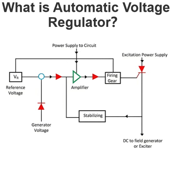
What is Automatic Voltage Regulator?
An automatic voltage regulator is employed to regulate voltage, converting fluctuating voltages into a constant one. Voltage fluctuations mainly stem from variations in the load on the supply system. Such voltage variations can damage the equipment within the power system. These fluctuations can be mitigated by installing voltage - control equipment at various locations, such as near transformers, generators, and feeders. Multiple voltage regulators are often placed throughout the power system t
Edwiin
05/22/2025
Inquiry
Download
Experts Electrical is dedicated to serving the personnel in the global power industry.
Join Experts Electrical, not only can you discover power equipment and power knowledge, but also canhnd like - minded friends!