Motor Thermal Overload Protection
Motor thermal overload protection set
Thermal overload protection is a safety mechanism that prevents the motor from overheating by detecting excessive current and stopping the motor.
Cause of overheating
When considering motor overheating, the first cause that comes to mind is overload. Mechanical overload causes the motor to consume a higher current, which leads to overheating. If the rotor is locked by external forces, consuming too much current, the motor will also overheat. Low supply voltage is another reason; The motor consumes more current to maintain torque. When one power supply phase fails, the single phase and the power supply are unbalanced, resulting in negative sequence current, which can also lead to overheating. When the motor accelerates to its rated speed, the sudden loss and recovery of voltage can lead to overheating, which consumes a large current.
Since thermal overload or overheating of the motor can lead to insulation failure and winding damage, for proper motor thermal overload protection, the motor should be protected from the following conditions
Mechanical overload
Motor shaft is blocked
Low supply voltage
Single-phase power supply
Power unbalance
Sudden loss and reconstruction of supply voltage
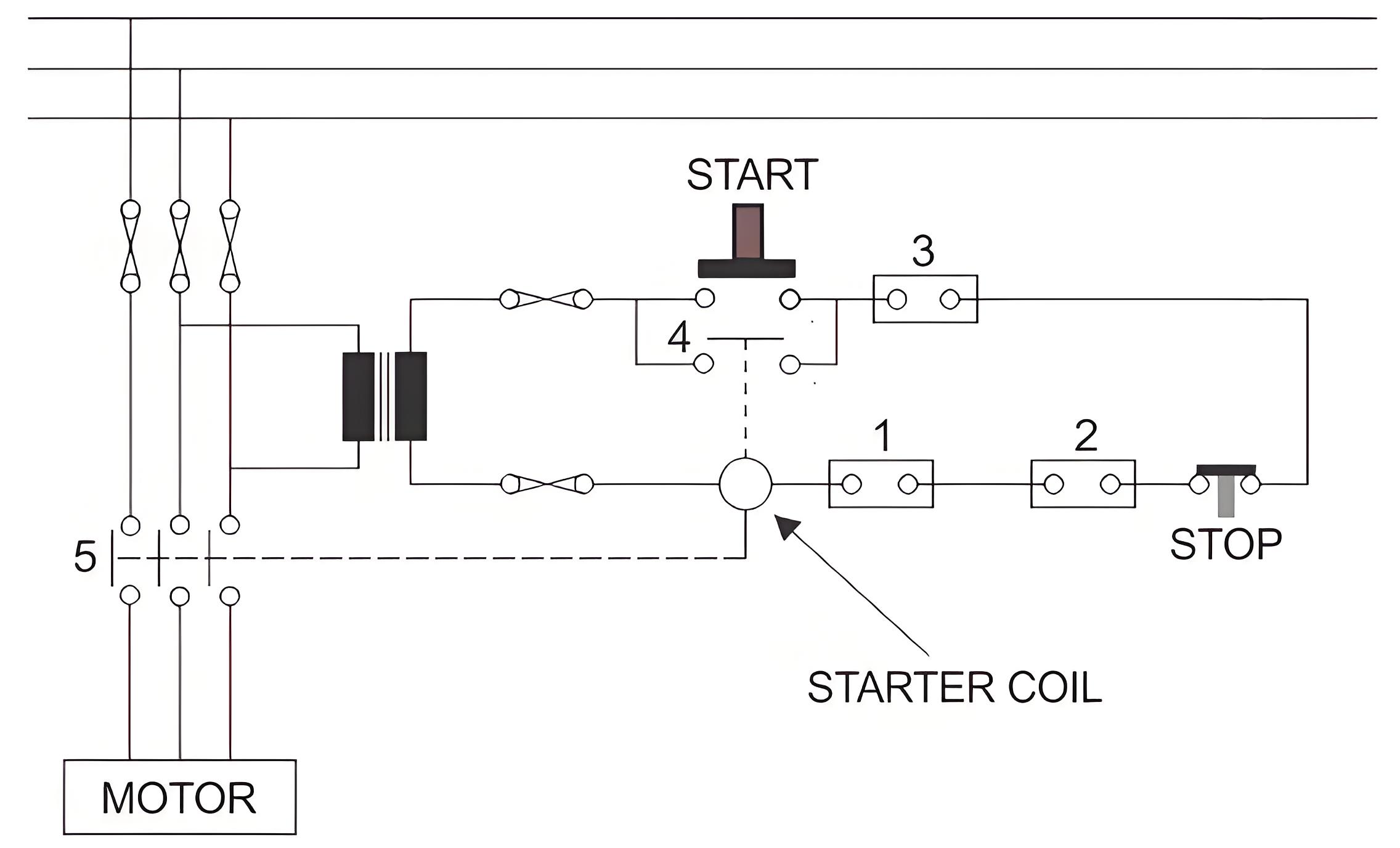
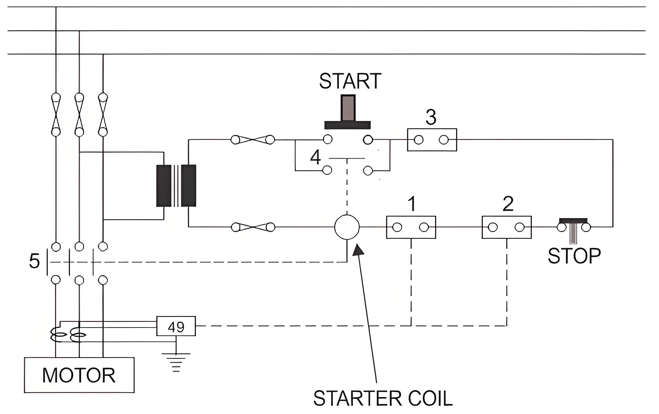
The most basic protection scheme of the motor is thermal overload protection, which mainly covers the protection of all the above situations. In order to understand the basic principle of thermal overload protection, let's look at the schematic diagram of the basic motor control scheme.
In the figure above, when the START push is closed, the start coil is energized through the transformer. When the starting coil is energized, the normally open (NO) contact 5 closes, so the motor obtains the supply voltage at its terminals and begins to rotate. The START coil also closes contact 4, energizing the start coil even if the Start button contact is released from its closed position.
To stop the motor, there are several normally closed (NC) contacts in series with the starting coil, as shown in the figure. One of them is the STOP button contact. If the STOP button is pressed, this button contact will open and disconnect the continuity of the starting coil circuit, resulting in a power failure of the starting coil.
Thus, contacts 5 and 4 return to their normal open positions. Then, in the absence of voltage at the motor terminals, it will eventually stop running. Similarly, any other NC contacts (1, 2, and 3), if opened, are connected in series with the starting coil; It will also stop the motor. These NC contacts are electrically coupled with various protective relays to stop the operation of the motor under different abnormal conditions
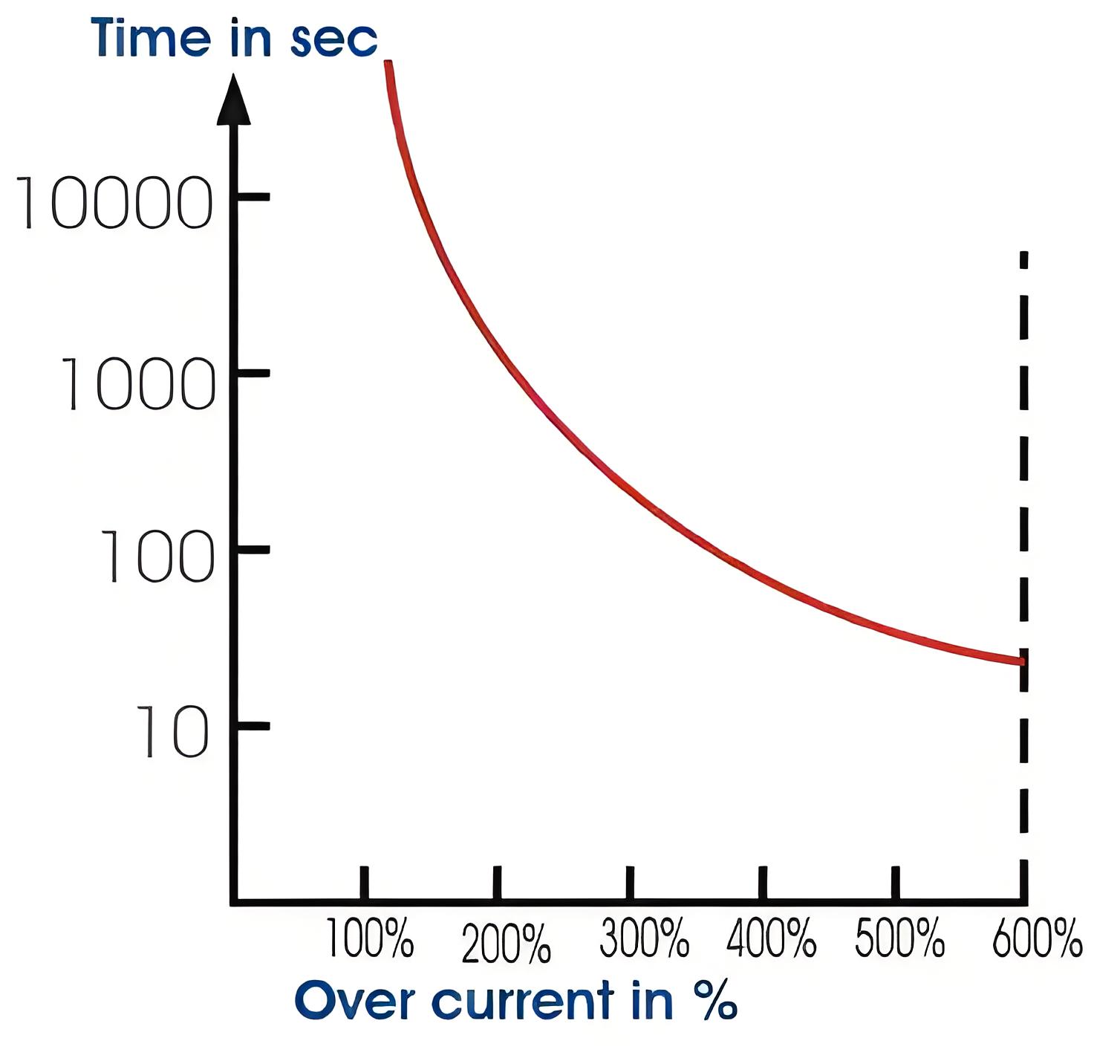
Another important point of motor thermal overload protection is the predetermined overload tolerance value of the motor. Each motor can operate for a period of time in excess of its rated load according to load conditions specified by the manufacturer. This relationship between motor load and safe operating time is shown in the thermal limit curve. Here is an example of such a curve.
Here the Y-axis or the vertical axis represents the allowable time in seconds, and the X-axis or the horizontal axis represents the overload percentage. It is clear from the curve that the motor can operate safely at 100% rated load for a long time without causing any damage due to overheating. It can operate safely for 1000 seconds at 200% of its normal rated load. It can operate safely for 100 seconds at 300% of normal rated load.
It can operate safely for 600 seconds at 15% of its normal rated load. The top half of the curve indicates the normal operating conditions of the rotor, and the bottom half indicates the mechanical locking state of the rotor
Thermal overload relay
The relay uses bimetal sheets that heat up and bend when the current is too high, breaking the circuit to stop the motor.
Thermal limiting curve
This curve shows how long the motor can operate at different overload levels without damage, helping to set protection limits.
RTD Advanced protection
Resistance temperature detectors (RTDS) provide precise motor protection by monitoring temperature changes and triggering protection measures.
The Electricity Encyclopedia is dedicated to accelerating the dissemination and application of electricity knowledge and adding impetus to the development and innovation of the electricity industry.
