Electrical Fault Calculation
Electrical Fault Calculation Definition
Electrical fault calculation involves determining the maximum and minimum fault currents and voltages at different points in a power system to design protective systems.
Positive Sequence Impedance
Positive sequence impedance is the resistance faced by positive sequence current, crucial for calculating three-phase faults.
Negative Sequence Impedance
Negative sequence impedance is the resistance faced by negative sequence current, important for understanding unbalanced fault conditions.
Zero Sequence Impedance
The impedance offered by the system to the flow of zero sequence current is known as zero sequence impedance.In previous fault calculation, Z1, Z2 and Z0 are positive, negative and zero sequence impedance respectively. The sequence impedance varies with the type of power system components under consideration:-
In static and balanced power system components like transformer and lines, the sequence impedance offered by the system are the same for positive and negative sequence currents. In other words, the positive sequence impedance and negative sequence impedance are same for transformers and power lines.But in case of rotating machines the positive and negative sequence impedance are different.
The assignment of zero sequence impedance values is a more complex one. This is because the three zero sequence current at any point in a electrical power system, being in phase, do not sum to zero but must return through the neutral and /or earth. In three phase transformer and machine fluxes due to zero sequence components do not sum to zero in the yoke or field system. The impedance very widely depending upon the physical arrangement of the magnetic circuits and winding.
The reactance of transmission lines of zero sequence currents can be about 3 to 5 times the positive sequence current, the lighter value being for lines without earth wires. This is because the spacing between the go and return(i.e. neutral and/or earth) is so much greater than for positive and negative sequence currents which return (balance) within the three phase conductor groups.
The zero sequence reactance of a machine is compounded of leakage and winding reactance, and a small component due to winding balance (depends on winding tritch).The zero sequence reactance of transformers depends both on winding connections and upon the construction of the core.
Symmetrical Component Analysis
The above fault calculation is made on assumption of three phase balanced system. The calculation is made for one phase only as the current and voltage conditions are same in all three phases.
When actual faults occur in electrical power system, such as phase to earth fault, phase to phase fault and double phase to earth fault, the system becomes unbalanced means, the conditions of voltages and currents in all phases are no longer symmetrical. Such faults are solved by symmetrical component analysis.
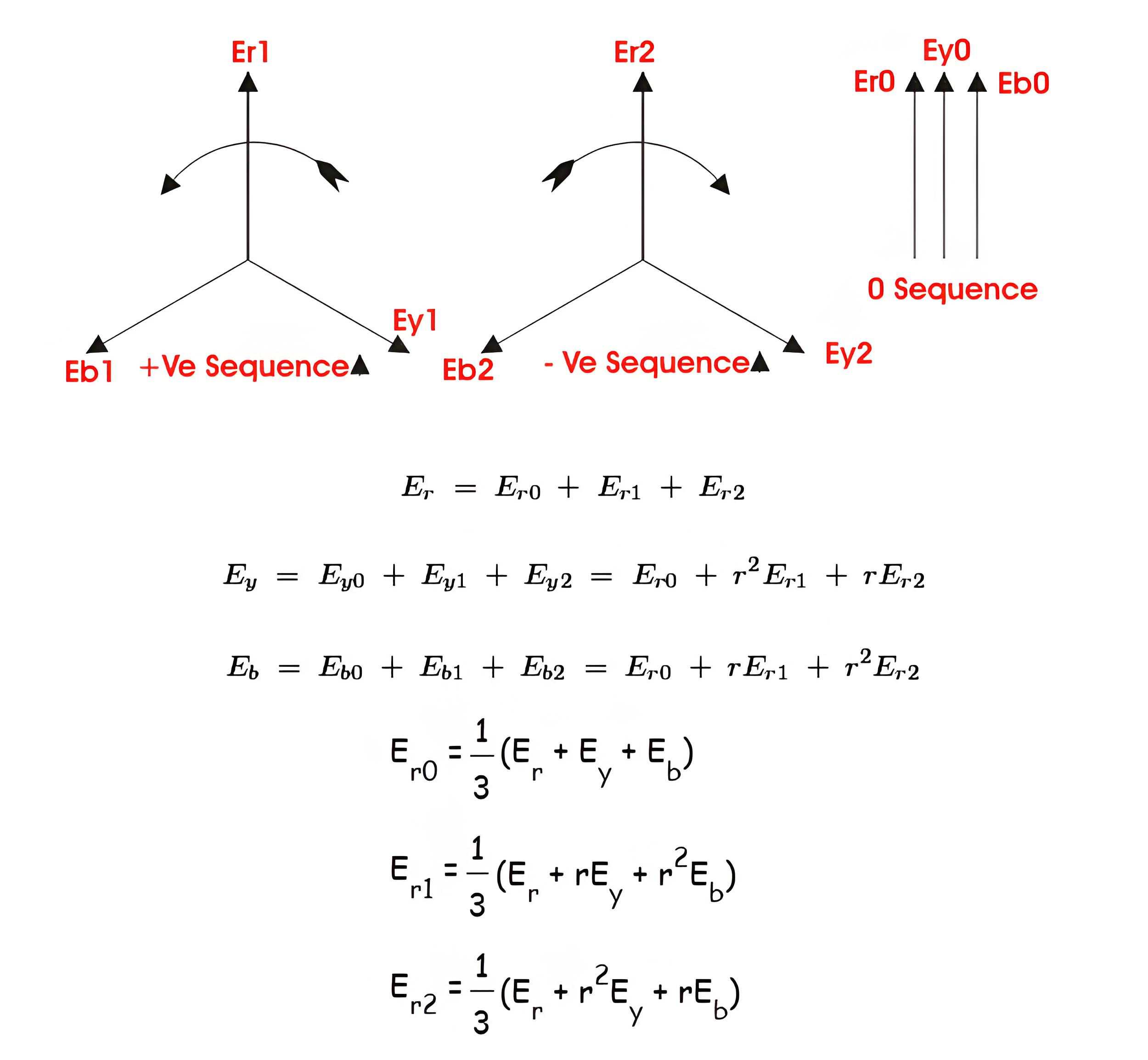
Generally three phase vector diagram may be replaced by three sets of balanced vectors. One has opposite or negative phase rotation, second has positive phase rotation and last one is co-phasal. That means these vectors sets are described as negative, positive and zero sequence, respectively.
Where all quantities are referred to the reference phase r.Similarly a set of equations can be written for sequence currents also. From, voltage and current equations, one can easily determine the sequence impedance of the system.
The Electricity Encyclopedia is dedicated to accelerating the dissemination and application of electricity knowledge and adding impetus to the development and innovation of the electricity industry.
