Backup Protection of Transformers
Backup Protection
These over current and earth Fault relays may be of Inverse Definite Minimum Time (IDMT) or Definite Time type relays (DMT). Generally IDMT relays are connected to the in-feed side of the transformer.
Overcurrent relays cannot differentiate between external short circuits, overloads, and internal faults of the transformer. Backup protection, using overcurrent and earth fault protection on the in-feed side, will activate for any of these faults.
Backup protection is usually installed on the in-feed side of the transformer, but it should trip both the primary and secondary circuit breakers.
Overcurrent and earth fault protection relays can also be placed on the load side of the transformer. However, they should not trip the primary side circuit breaker like the backup protection on the in-feed side.
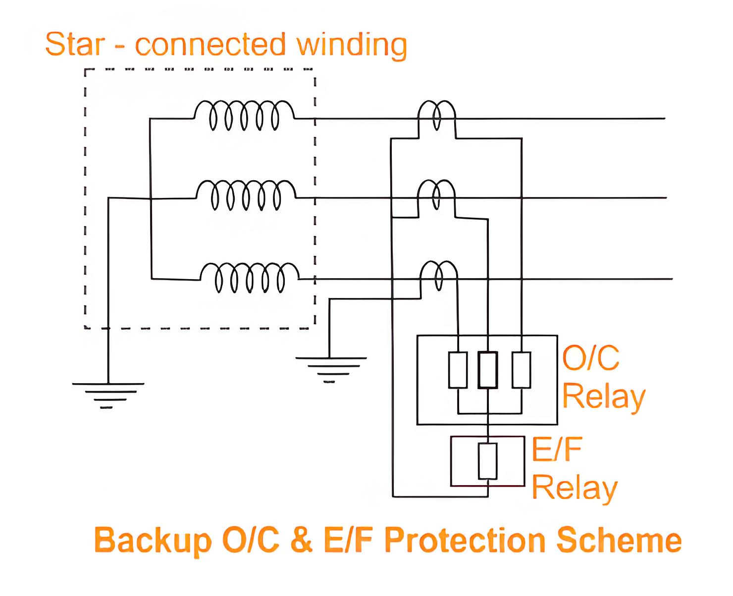
The operation of these relays is governed by current and time settings, along with the relay’s characteristic curve. This allows the use of the transformer overload capacity and coordination with other relays at about 125% to 150% of the full load current, but below the minimum short circuit current.
Backup protection of transformer has four elements; three over current relays connected each in each phase and one earth fault relay connected to the common point of three over current relays as shown in the figure. The normal range of current settings available on IDMT over current relays are 50% to 200% and on earth fault relay 20 to 80%.
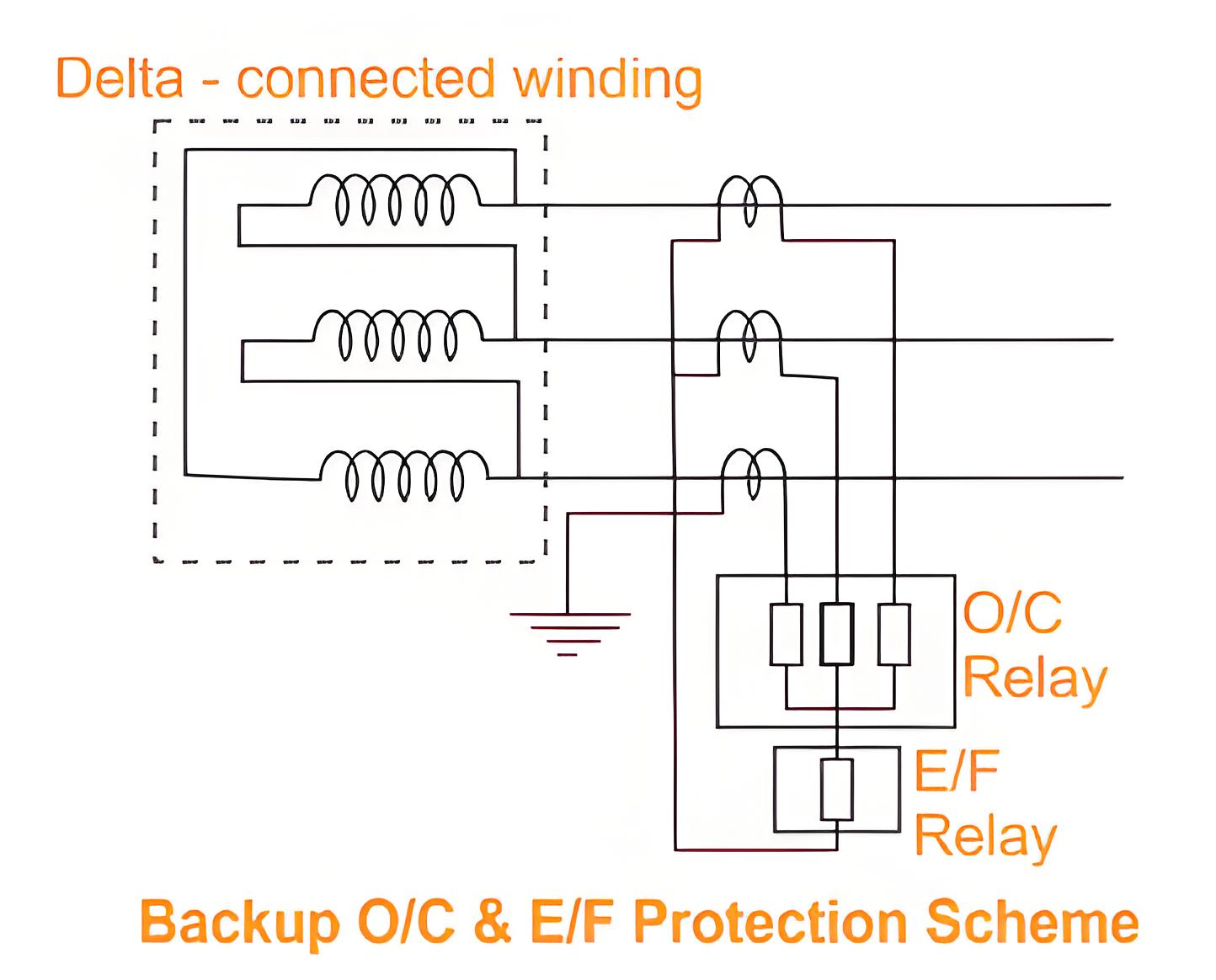
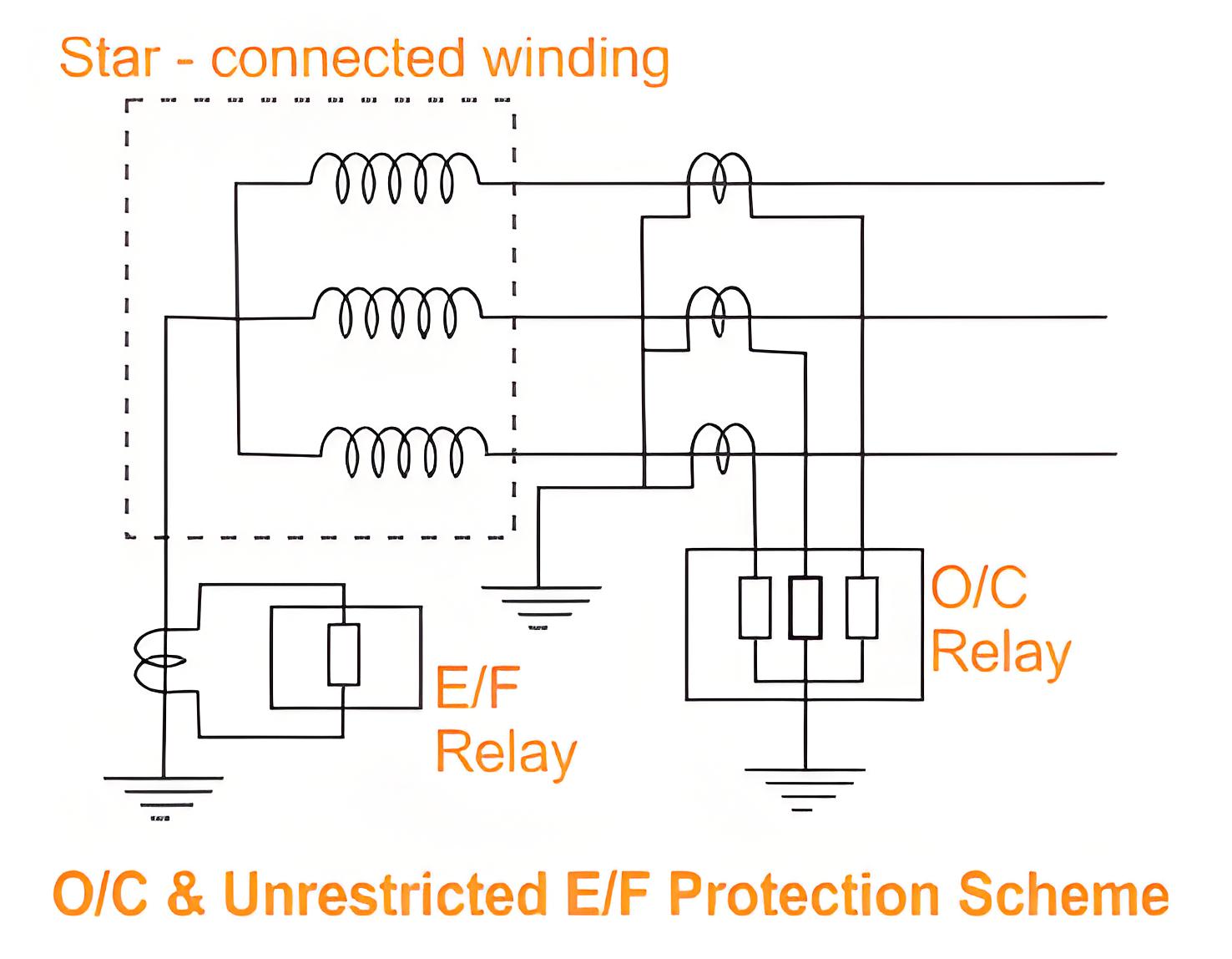
Another range of setting on earth fault relay is also available and may be selected where the earth fault current is restricted due to insertion of impedance in the neutral grounding. In the case of transformer winding with neutral earthed, unrestricted earth fault protection is obtained by connecting an ordinary earth fault relay across a neutral current transformer.
The unrestricted over current and earth fault relays should have proper time lag to co-ordinate with the protective relays of other circuit to avoid indiscriminate tripping.
The Electricity Encyclopedia is dedicated to accelerating the dissemination and application of electricity knowledge and adding impetus to the development and innovation of the electricity industry.

