Tuned Collector Oscillator
Tuned Collector Oscillator Definition
A tuned collector oscillator is defined as an LC oscillator that uses a tank circuit and a transistor to generate a periodic signal.
Circuit Diagram Explanation
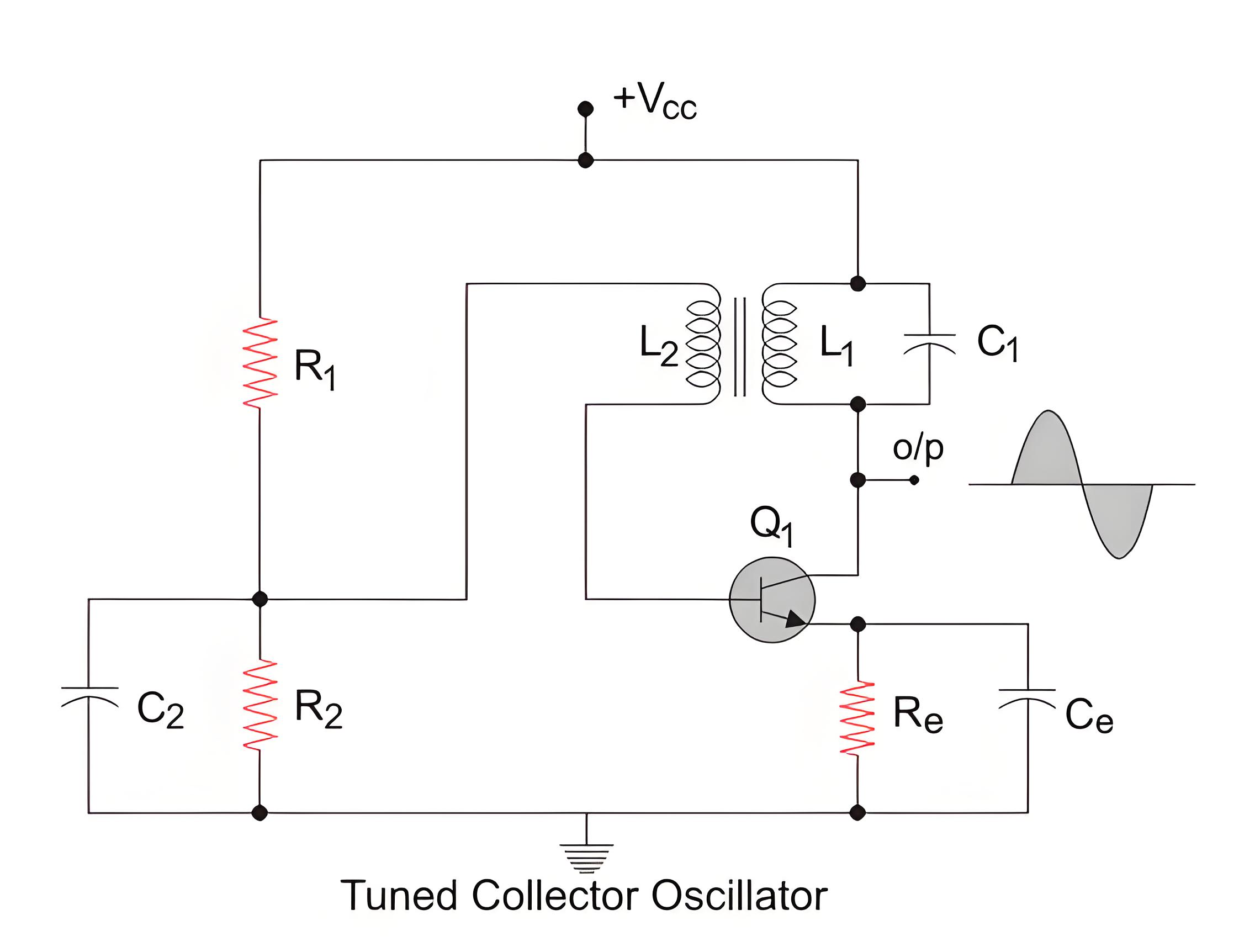
The circuit diagram shows the tuned collector oscillator. The transformer and capacitor are connected to the transistor’s collector, producing a sine wave.
R1 and R2 form the voltage divider bias for the transistor. Re refers to the emitter resistor and is there to provide thermal stability. Ce is used to bypass the amplified ac oscillations and is the emitterbypass capacitor. C2 is the bypass capacitor for resistor R2. The primary of the transformer, L1 along with capacitor C1 forms the tank circuit.
Working of Tuned Collector Oscillator
Before we go into the working of the oscillator, let us just revise the fact that a transistor causes a phase shift of 180 degrees when it amplifies an input voltage. L1 and C1 form the tank circuit and it is from these two elements, we will get the oscillations. The transformer helps in giving a positive feedback(We will come back to this later) and the transistor amplifies the output. With that established, let us now proceed to understand the working of the circuit.
When the power supply is switched on, the capacitor C1 starts charging. When it is fully charged, it starts to discharge through the inductor L1. The energy stored in the capacitor in the form of electrostatic energy gets converted to electromagnetic energy and gets stored in the inductor L1. Once the capacitor discharges completely, the inductor starts charging the capacitor again.
This is because inductors do not the current through them change quickly and hence it will change the polarity across itself and keep the current flowing in the same direction. The capacitor starts charging again and the cycle continues in this manner. The polarity across the inductor and capacitor changes periodically and hence we get an oscillating signal as the output.
Coil L2 charges through electromagnetic induction and sends this to the transistor. The transistor amplifies the signal, producing the output. A portion of this output is fed back into the system as positive feedback.
Positive feedback is the feedback which is in phase with the input. The transformer introduces a phase shift of 180 degrees and the transistor also introduces a phase shift of 180 degrees too. So in total, we get a 360-degree phase shift and this is fed back to the tank circuit. Positive feedback is necessary for sustained oscillations.
The frequency of oscillation depends on the value of the inductor and capacitor used in the tank circuit and is given by:
Where,
F = Frequency of the oscillation. L 1 = value of the inductance of primary of the transformer L1.C1 = value of capacitance of capacitor C1.

The Electricity Encyclopedia is dedicated to accelerating the dissemination and application of electricity knowledge and adding impetus to the development and innovation of the electricity industry.
