Measurement of Three Phase Power
Three Phase Power Measurement Definition
Three phase power measurement involves using different methods to determine the total power in a three-phase circuit, depending on the number of wattmeters used.
Three Wattmeters Method
Uses three wattmeters connected to each phase and neutral line in a four-wire system to measure total power by summing individual readings.
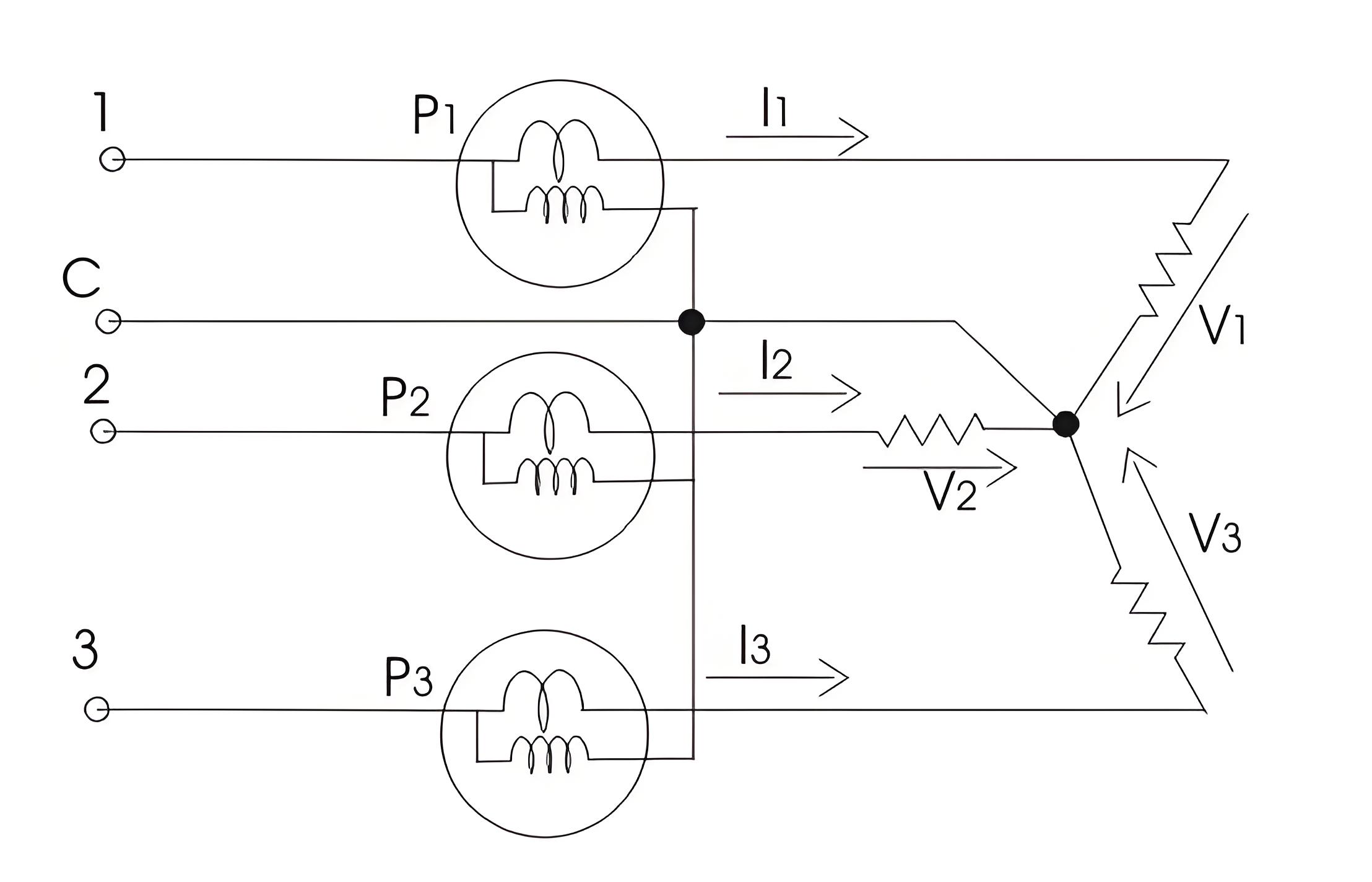
The circuit diagram is shown below-
This method is used for three-phase four-wire systems. The coils of the three wattmeters are connected to the respective phases, marked 1, 2, and 3. The pressure coils are connected to a common neutral point. Each wattmeter measures the product of phase current and line voltage (phase power). The total power is the sum of all wattmeter readings.

Two Wattmeters Method
Employs two wattmeters and can be used for both star and delta load connections, summing the readings to determine total power.
Star connection of loads
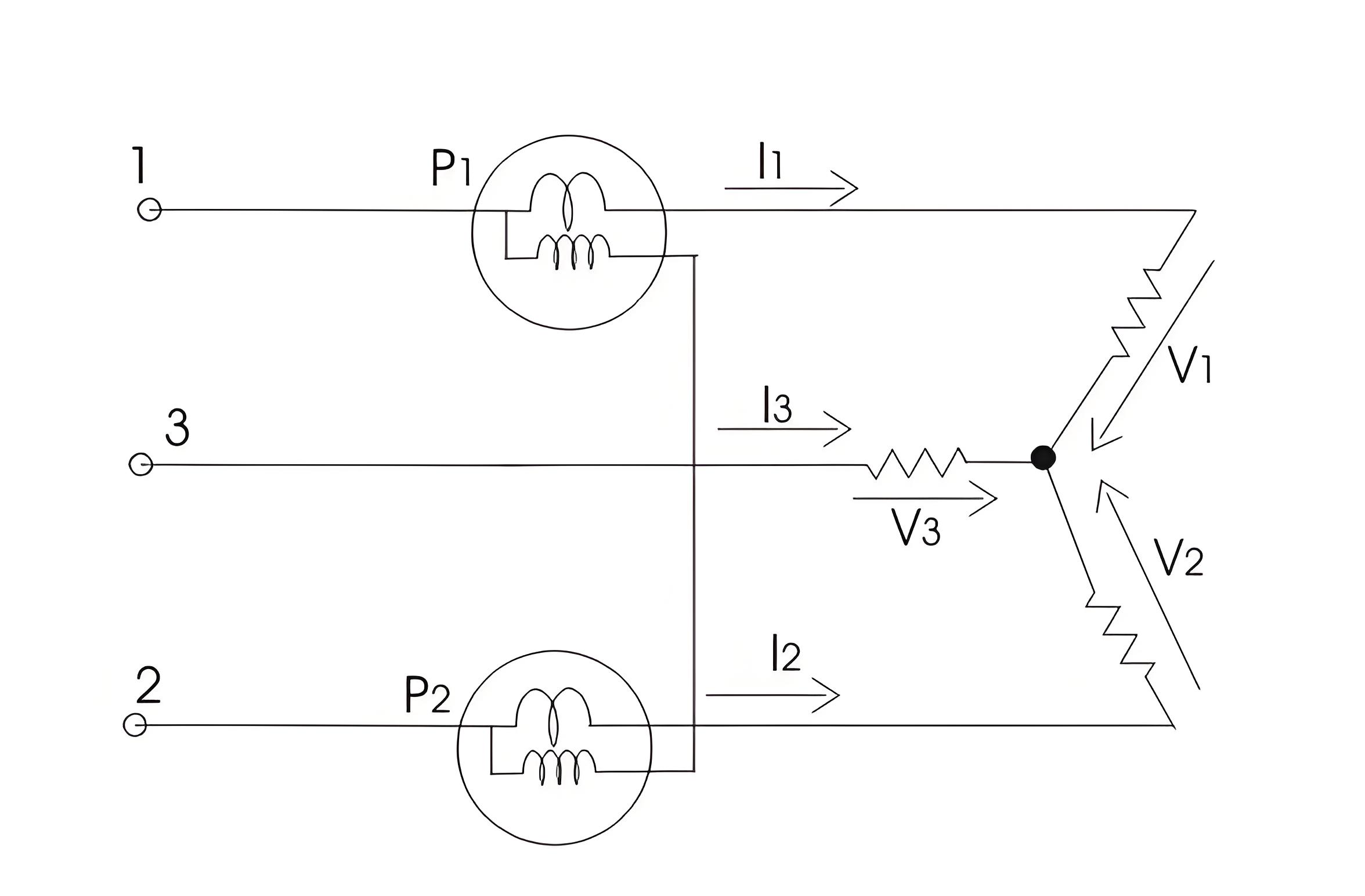
When the load is star connected load, the diagram is shown in below-
For star connected load clearly the reading of wattmeter one is product of phase current and voltage difference (V2-V3). Similarly the reading of wattmeter two is the product of phase current and the voltage difference (V2-V3). Thus the total power of the circuit is sum of the reading of both the wattmeters. Mathematically we can write
but we have , hence putting the value of .

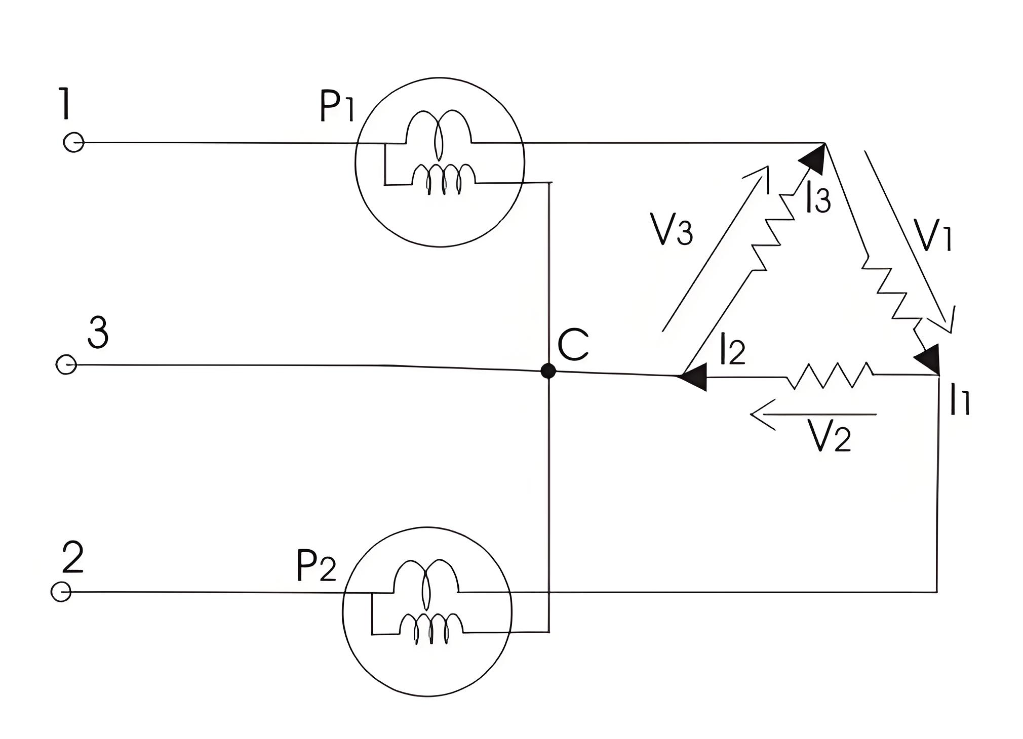
When delta connected load, the diagram is shown in below
The reading of wattmeter one can be written as
and reading of wattmeter two is
but , hence expression for total power will reduce to .

One Wattmeter Method
Suitable only for balanced loads, using one wattmeter and switching between phases to measure power.
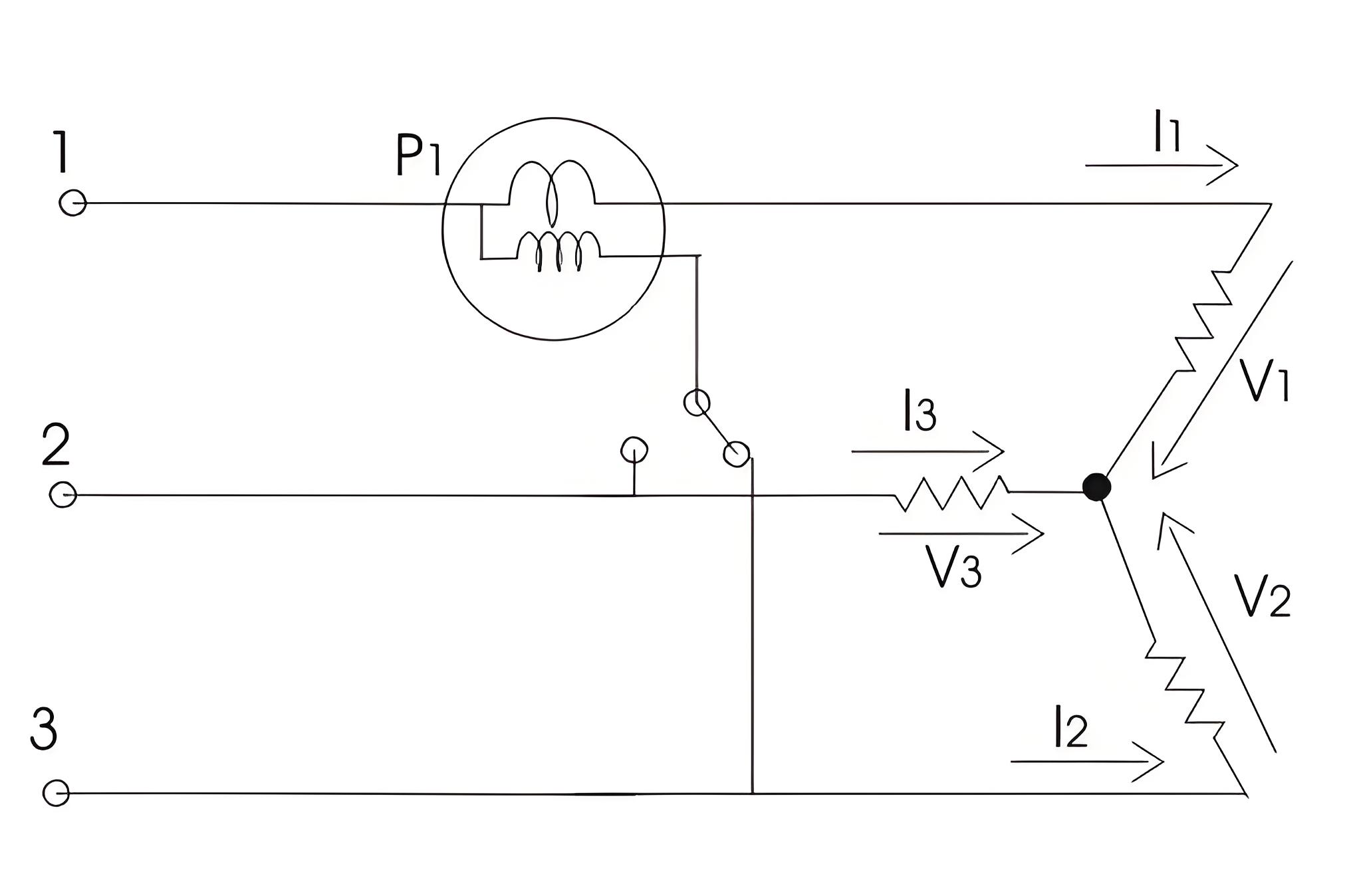
Limitation of this method is that it cannot be applied on unbalanced load. So under this condition we have .
Diagram is shown below:
Two switches are used, labeled 1-3 and 1-2. Closing switch 1-3 gives the wattmeter reading as
Similarly the reading of wattmeter when switch 1-2 is closed is

The Electricity Encyclopedia is dedicated to accelerating the dissemination and application of electricity knowledge and adding impetus to the development and innovation of the electricity industry.

