How to Use a Digital Multimeter?
How to Use a Digital Multimeter?
Digital Multimeter Definition
A digital multimeter is defined as a device that measures electrical parameters like voltage, current, and resistance, displaying the results digitally.
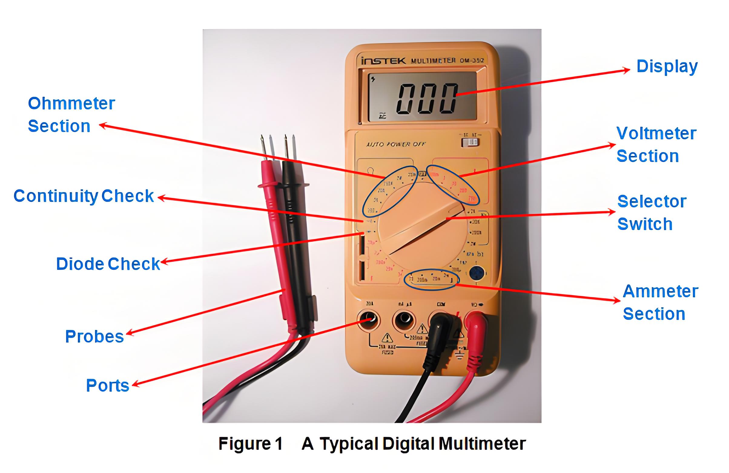
Main Parts
The main parts of a digital multimeter include the display, selection switch, ports, and probes, each crucial for accurate measurements.
Measuring Current
To measure current with a digital multimeter, it mimics an ammeter. Insert the red probe into the mA socket for low current or the 20A socket for high current. Connect the meter in series with the circuit. Set the switch to the expected current range. When the power is on, the meter will display the current flowing through the circuit.
Measuring Voltage
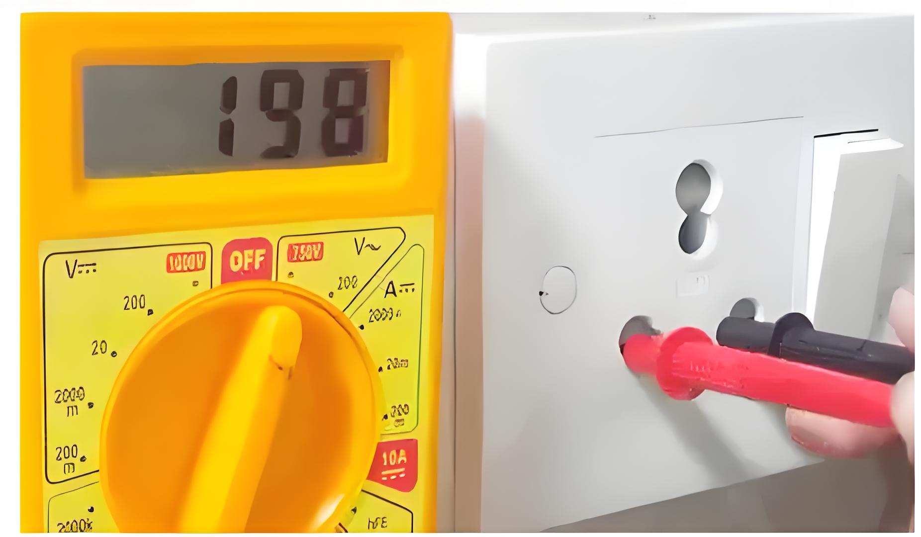
To measure voltage with a digital multimeter, it acts like a voltmeter. Insert the red probe into the ‘V’ socket and the black probe into the ‘COM’ socket. Select the expected voltage range and choose either AC or DC. Connect the leads in parallel with the component or point where the voltage is measured. The meter will display the voltage value.
Measuring Resistance
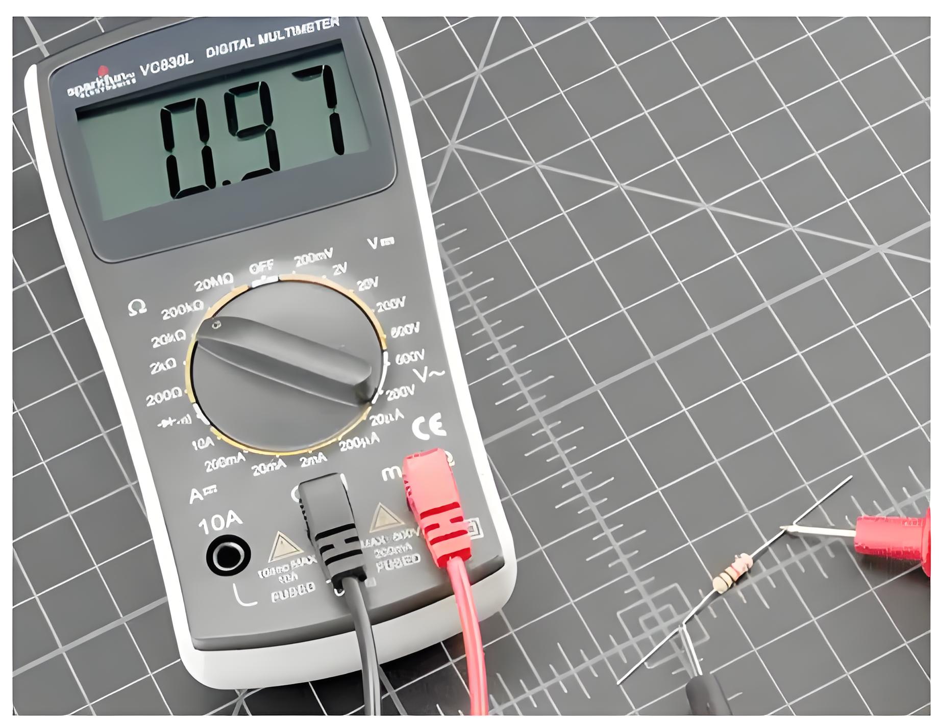
In this case, we configure the multimeter to act like an ohmmeter. Here the red and the black probes of the multimeter are inserted into the sockets marked as ‘V’ and ‘COM’, respectively while the selection switch is set to an expected range in ohmmeter region (Figure 1). Now, the leads need to be connected across the component whose resistance is to be known. On doing so, we get a reading in the display part of the multimeter which reads the value of the resistance.
Diode Check
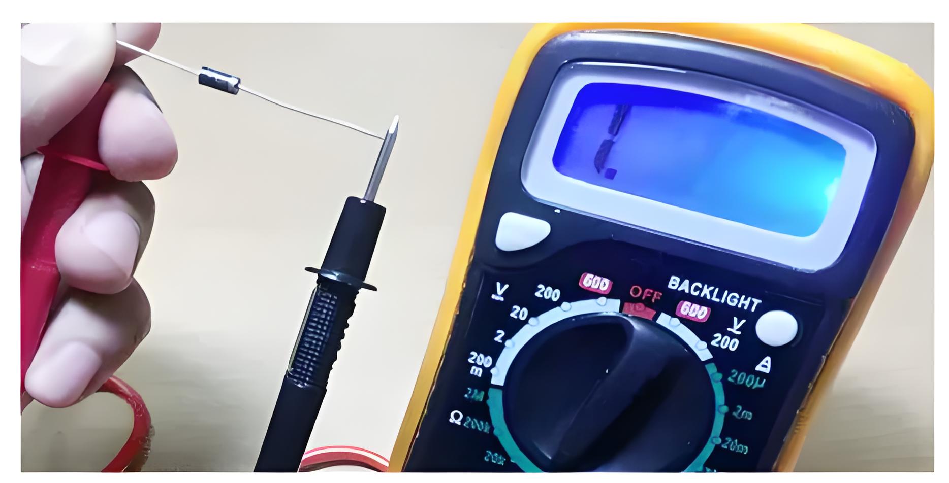
For this case, insert the probes into the sockets as that in the case of voltage measurement and set the selection switch to point towards diode check position shown in Figure 1. Now when the red lead of the multimeter is connected to positive terminal of the diode while its negative lead is connected to the negative terminal of the diode, then we have to get a low reading on the multimeter.
On the other hand, if we connect the red lead to the negative terminal of the diode and the black to the positive terminal, then we have to get a high value. If the readings obtained are as per our expectation, then we say that the diode is working properly; else no.
Checking Continuity
Continuity check is used to know whether there exists any low resistance path via two points i.e. to check whether the points are short or not. To accomplish this task, the probes are inserted into the sockets as that in the case of voltage measurement and selector switch is made to point towards continuity check position (Figure 1). Then, the points to be tested are touched with the leads of the probes. Now, if the multimeter beeps out, then it means that the points are shorted or else the resistance between them can be read out from the display.
The Electricity Encyclopedia is dedicated to accelerating the dissemination and application of electricity knowledge and adding impetus to the development and innovation of the electricity industry.
