What are Induction Type Meters?
Induction Type Meters Definition
Induction type meters are devices used to measure electrical energy in homes and industries by using the interaction of fluxes and alternating currents.
Working Principle
The working principle and construction of an induction type meter are simple and easy to understand, making them popular for measuring energy in homes and industries. In all induction meters, two fluxes are produced by different alternating currents on a metallic disc. These alternating fluxes create an induced emf. This emf interacts with the alternating current on the opposite side, producing torque.
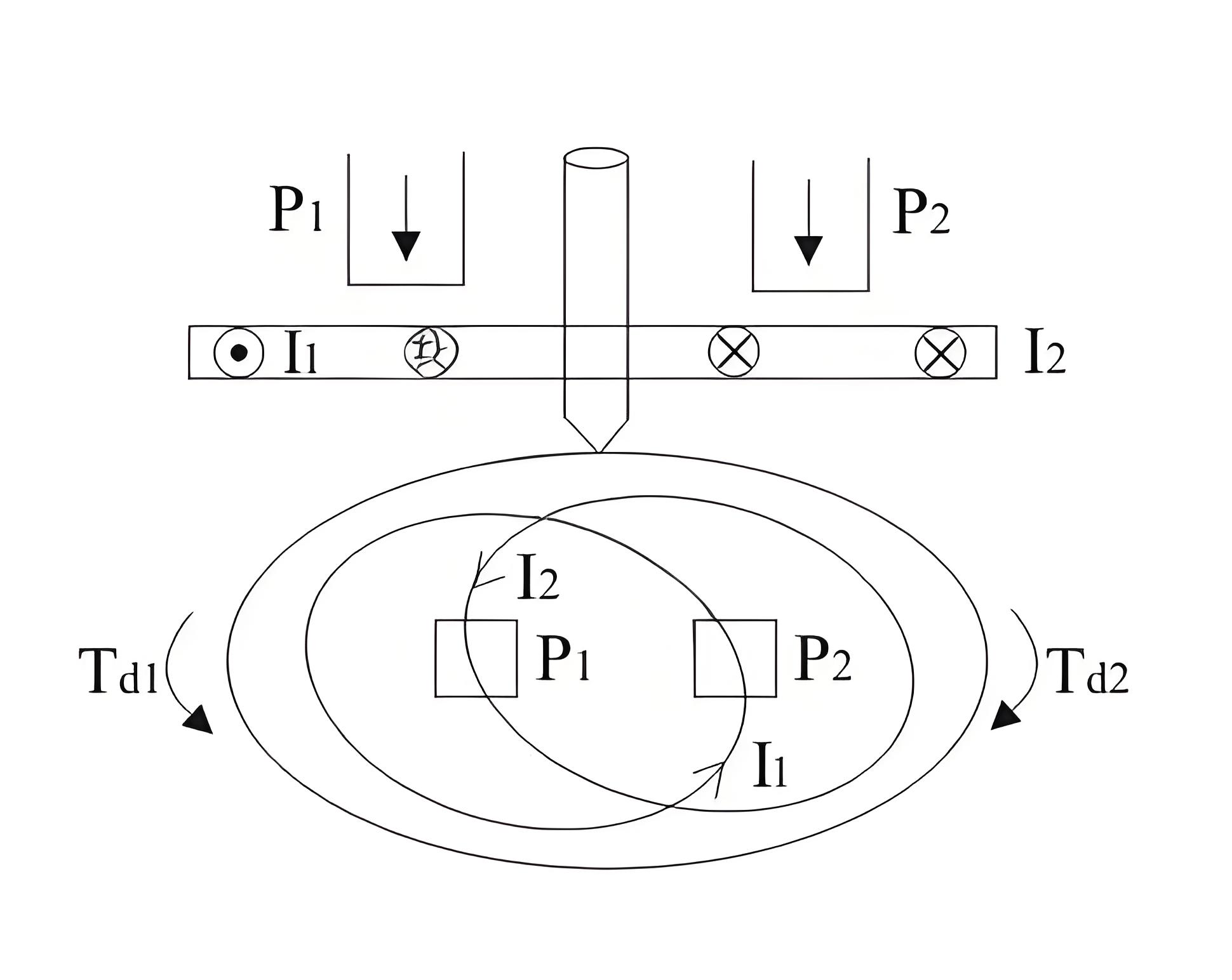
Similarly, the emf produced at point two interacts with the alternating current at point one, creating torque in the opposite direction. These opposing torques cause the metallic disc to move.
This is basic principle of working of an induction type meters. Now let us derive the mathematical expression for deflecting torque. Let us take flux produced at point one be equal to F1 and the flux and at point two be equal to F2. Now the instantaneous values of these two flux can written as:

Where, Fm1 and Fm2 are respectively the maximum values of fluxes F1 and F2, B is phase difference between two fluxes.We can also write the expression for induced emf’s at point one be at point two.

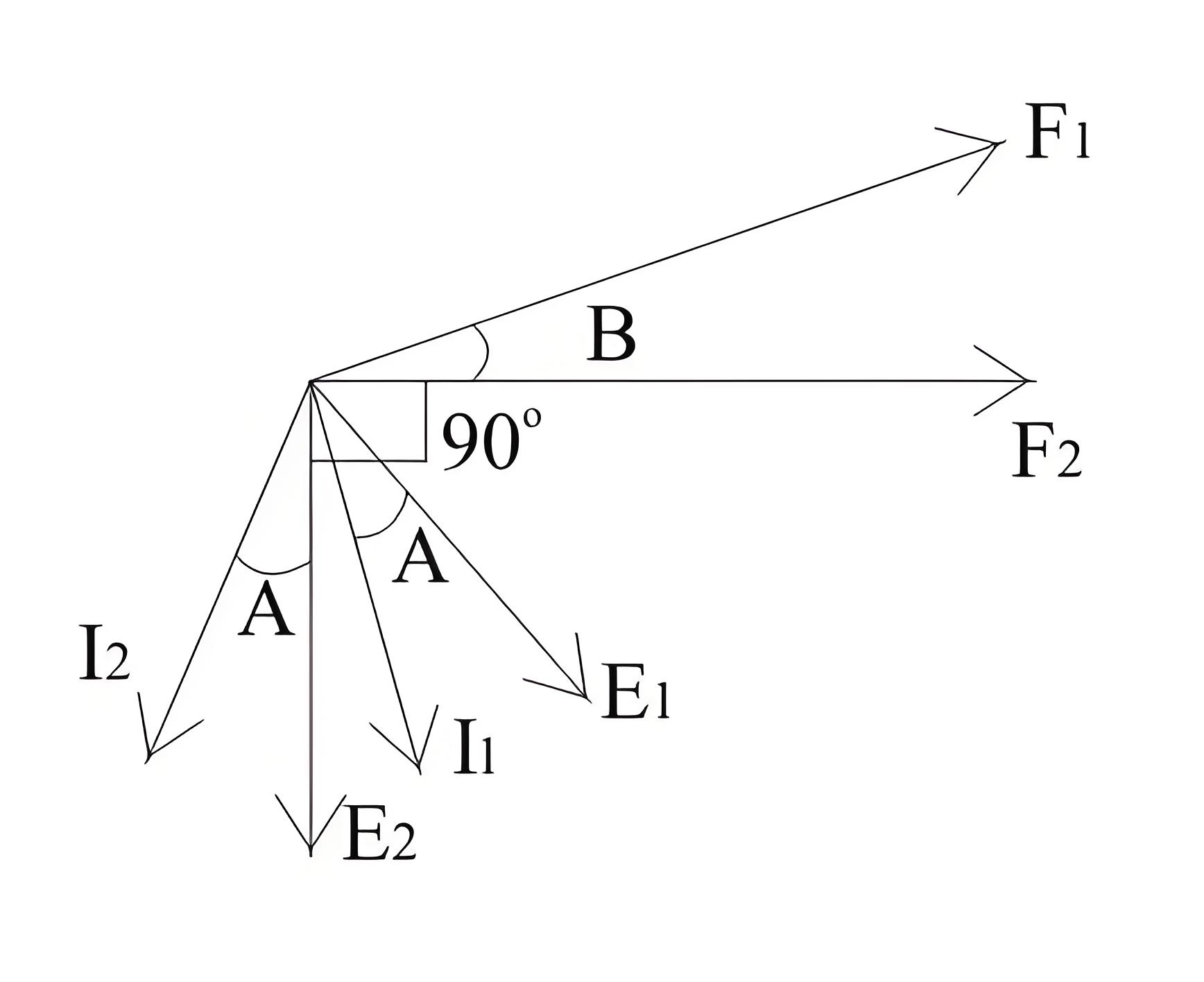
Where, K is some constant and f is frequency.Let us draw phasor diagram clearly showing F 1, F2, E1, E2, I1 and I2. From phasor diagram, it clear that I1 and I2 are respectively lagging behind E1 and E2 by angle A.

The angle between F1 and F2 is B. From the phasor diagram the angle between F2 and I1 is (90-B+A) and the angle between F1 and I2 is (90 + B + A). Thus we write the expression for deflecting torque as,Similarly the expression for T d2 is

The total torque is T d1 – Td2, on substituting the the value of Td1 and Td2 and simplying the expression we get

Types of Induction Meters
The two main types are single phase and three phase induction meters.
Which is known as the general expression for the deflecting torque in the induction type meters. Now there are two types of induction meters and they are written as follows:

Single phase type
Three phase type induction meters.
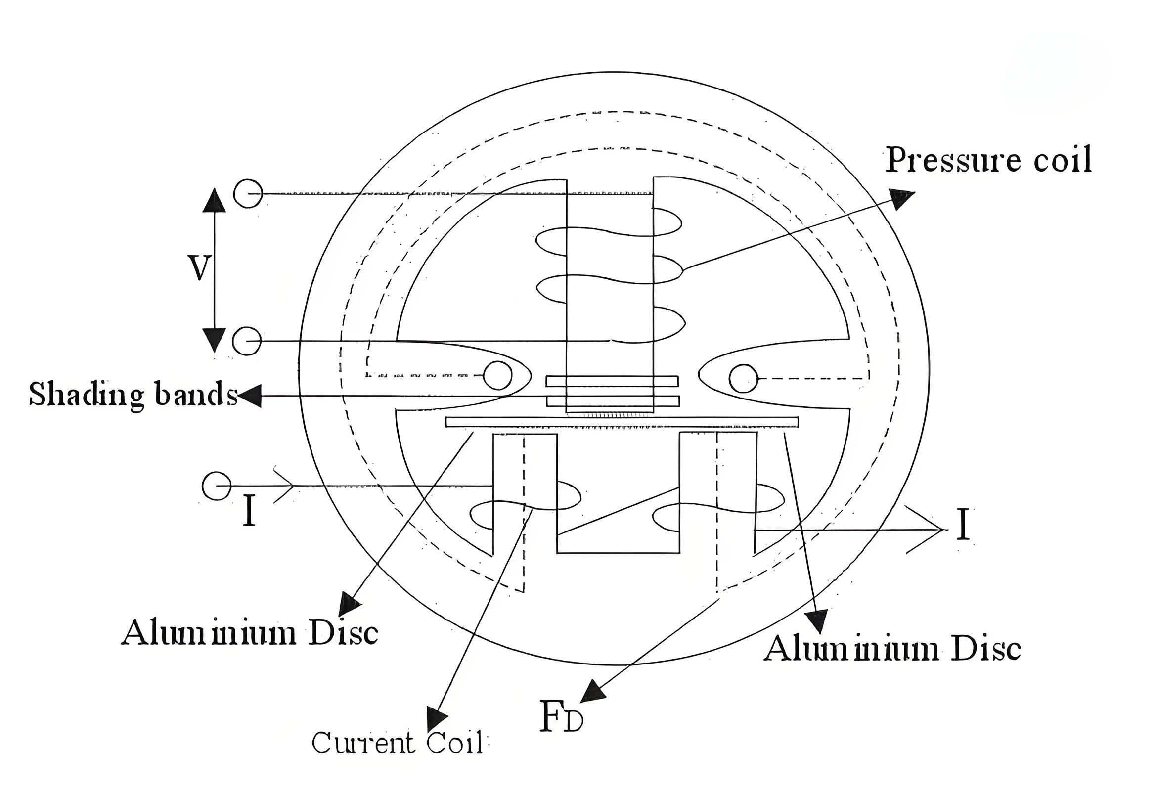
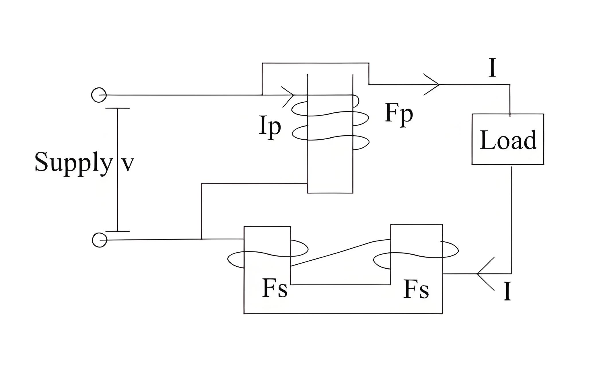
Single Phase Meter Components
Key parts include the driving system with electromagnets, a floating aluminum disc in the moving system, a braking system with a permanent magnet, and a counting system to record revolutions.
Advantages
They are inexpensive as compared to moving iron type instruments.
They have high torque is to weight ratio as compared to other instruments.
They retain their accuracy over wide range of temperature as well as loads.
The Electricity Encyclopedia is dedicated to accelerating the dissemination and application of electricity knowledge and adding impetus to the development and innovation of the electricity industry.
