Good operating practices for switchgear circuit breakers and contactors

James
04/09/2025
Good operating practices for switchgear circuit breakers and contactors
Operation of LV/MV Switchgear
The aim of this guideline is to offer recommended practices for the operation and inspection of medium - voltage (2 - 13.8 kV) and low - voltage (200 - 480 V) draw - out switchgear circuit breakers and contactors. Well - regulated operation is of utmost importance for maximizing the performance and service of plant equipment, as well as ensuring a safe working environment for plant personnel.

This article delineates the responsibilities of operating personnel, along with their daily checks and inspections of switchgear. Additionally, it will expound on the optimal practices for the operation and protection of transformers, motors, buses, cables, circuit breakers, and contactors.
-
Operator Inspections
It is the operating personnel's duty to set up and carry out regular routine inspections of all the switchgear in the plant. Circuit breakers, contactors, and busbars should be kept clean and dry to lower the risk of insulation failures that might lead to explosions and fires. Generally, it is advisable to conduct inspections once a day.
The following are the recommended daily inspection items for switchgear:- Check if the protective relay targets have dropped or been actuated. If any anomalies are found, reset them and record in the control room logbook.
- Listen for audible noise caused by electrical arcing.
- Detect any unusual smell from overheated or burning insulation.
- Look for signs of moisture intrusion, such as roof leaks or water on the floor.
- Ensure that status lamps and semaphore signals are working properly.
- Verify that the pressurizing room fans and dampers are functioning well to prevent moisture and other contaminants from entering.
- Confirm that the switchgear room doors are closed tightly to reduce the ingress of contaminants.
- Make sure that the switchgear cubicle doors are shut to reduce the ingress of contaminants.
- Check that the panels for accessing breaker racking mechanisms, cable terminations, and other purposes are closed to reduce the ingress of contaminants.
- Ensure that circuit breakers and contactors are stored in their respective cubicles or in special enclosures (usually equipped with heaters) to keep the equipment clean and dry.
- Check that the lighting in the switchgear room is working properly.
- Confirm that the cubicle labeling complies with the plant's regulations and accurately indicates the source, tie - line, and feeder positions.
- Ensure that rack - in tools and protective safety equipment are stored and maintained properly.
- Regularly perform cleaning tasks to keep the room clean and orderly.
If any anomalies are detected during the above - mentioned inspection process, maintenance work orders should be issued.
It will delve into the practices for load feeder overcurrent and ground fault protection, as well as source and tie overcurrent protection, and other crucial practices related to transformers.Furthermore, it will address switchgear bus transfers and explore the issues that arise during the paralleling of two power sources and in switch - time transfer schemes.

Protection
Protective relays are coordinated such that only those circuit breakers or contactors that need to operate to isolate faults will trip open automatically. This enables the maximum number of equipment to stay in operation, minimizing the impact on on - line generating units. It also gives an indication of the location of the electrical fault.
Electrical faults in transformers, motors, busbars, cables, circuit breakers, and contactors are typically permanent. Before re - energizing the equipment, a thorough investigation of the operation of protective relays must be carried out.
The magnitude of electrical short - circuit currents usually ranges from 15,000 to 45,000 amperes, depending on the size and impedance of the source transformer.
Load Feeder Ground Protection
Designs that limit the ground fault current (usually around 1000 amps) apply separate ground relays that will actuate for ground faults only. These relays trip with very short time delays to isolate the grounded feeders before source or tie circuit breaker ground relays can operate.
Source and Tie Overcurrent Protection
Source breakers and tie breakers are not equipped with instantaneous tripping elements. Instead, they rely on time delays to coordinate fault responses with downstream buses and loads.
Typically, these relays are set based on the maximum three - phase short - circuit current levels, with an operating time ranging from 0.4 to 0.8 seconds.
Normally, these relays feature an inverse - time characteristic. That is, lower current levels will result in proportionally longer time delays for all relays. Specifically, the tie breaker connected to another bus is set to operate in approximately 0.4 seconds, while the low - side breaker of the source transformer is set to operate in around 0.8 seconds.

High Side Source Transformer Overcurrent Protection
The overcurrent relays on the high - voltage side of the source transformer are typically set to operate approximately 1.2 seconds after a maximum three - phase short - circuit occurs on the low - voltage side. This time delay allows for proper coordination with the overcurrent relays on the low - voltage or secondary side.
These relays generally have an inverse - time characteristic, meaning that lower current levels result in longer operating times. The high - voltage - side overcurrent relays of the source transformer assume that a fault may occur in the transformer itself, in the low - voltage - side connecting buses or cables, or in the low - voltage circuit breaker. They will trip all necessary equipment to isolate the fault.
For Unitized Automatic Transfer Switches (UATs), which are usually equipped with differential protection, the high - voltage - side overcurrent relays can also cause the unit and the main step - up transformer to trip completely. Additionally, if the low - voltage - side breaker fails to interrupt a fault, the high - voltage - side overcurrent relays provide breaker - sticking protection.
Source and Tie Residual Ground Protection
For designs that limit the ground - fault current (usually around 1000 amps), separate ground relays are used, which actuate only in the event of a ground fault. The ground relays of source and tie breakers are not equipped with instantaneous tripping elements. Instead, they rely on time delays to coordinate fault responses with downstream buses and loads. Typically, these relays are set based on the maximum ground - fault current levels, with an operating time ranging from 0.7 to 1.1 seconds.
Normally, these relays exhibit an inverse - time characteristic. That is, lower current levels result in proportionally longer time delays for all relays. Specifically, the tie breaker connected to another bus is set to operate in approximately 0.7 seconds for 100% ground faults, while the low - side breaker of the source transformer is set to operate in around 1.1 seconds.
Source Transformer Neutral Ground Protection
In design schemes aimed at limiting the ground - fault current (usually around 1000 amps), dedicated ground relays are employed. These relays are specifically designed to accurately sense the ground current flowing through the neutral point of the transformer. They are highly targeted and will only be triggered when a ground fault occurs.
Normally, the source transformer neutral - ground relay is set to operate approximately 1.5 seconds after the most severe ground fault occurs. This time - delay setting is crucial as it ensures that the relay can coordinate well with the ground relays of the source breakers and tie breakers.
The neutral - ground relay has a crucial mission. Its core function is to isolate ground faults that occur on the low - voltage side (i.e., the secondary side) of the source transformer. Potential fault locations include the low - voltage windings of the transformer, low - voltage circuit breakers, and the buses and cables connecting them. More importantly, it also serves as a backup protection. In case the low - side breaker fails to function properly when facing a ground fault, the neutral - ground relay will promptly step in to cut off the faulty circuit, thereby ensuring the safe and stable operation of the power system.
Alarm - Only Ground Schemes
Alarm - only ground schemes restrict the ground - fault current to just a few amperes. Typical values are 1.1 amperes for 480 - volt systems and 3.4 amperes for 4 kV systems. For wye - connected source transformers, the neutral point is usually grounded via a grounding transformer. For delta - connected source transformers, the ground - fault current is typically supplied by three transformers, which are connected in a grounded wye configuration on the primary side and an open - delta configuration on the secondary side.
In both scenarios, voltage relays are installed on the secondary sides of the grounding transformers to alert for ground - fault conditions. In the case of delta - connected source transformers, blown primary fuses of the ground - detector transformers can also trigger an alarm.
Both relay schemes issue alarms (usually with a sensitivity of 10% or higher) for all grounded equipment within a specific electrical system. This includes the low - voltage or secondary windings of the source transformer, as well as all connected buses, cables, circuit breakers, potential transformers, and loads.
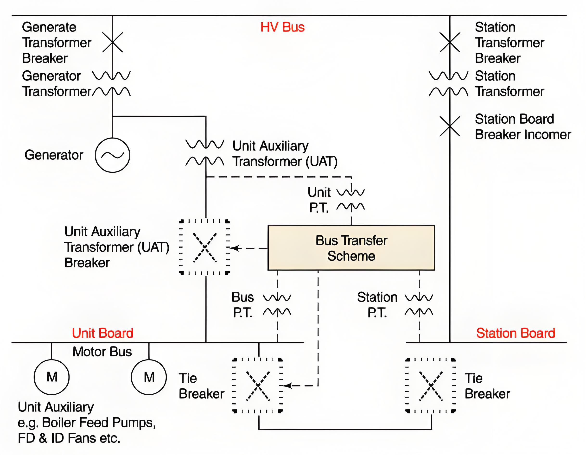
Switchgear Bus Transfers
Paralleling Two Sources
Paralleling two different power sources is the preferred approach for switching from one source to another. This method imposes no stress on motors, ensures a smooth transition, and poses no threat to the running equipment. However, in many designs, the short - circuit current generated during the paralleling process exceeds the interrupting capacity of feeder breakers.
Source breakers and tie breakers remain unaffected, but feeder breakers may fail to clear close - in faults and could even be damaged in the process. Therefore, the duration of paralleling should be minimized (around a few seconds) to reduce the exposure time and the probability of feeder faults.
Typically, this issue is more pronounced when a generating unit supplies power to one system while the standby or startup transformer is fed from a different system. Reducing the power output of the generator usually brings the phase angles closer together, as the generator's power angle decreases with the reduced load.
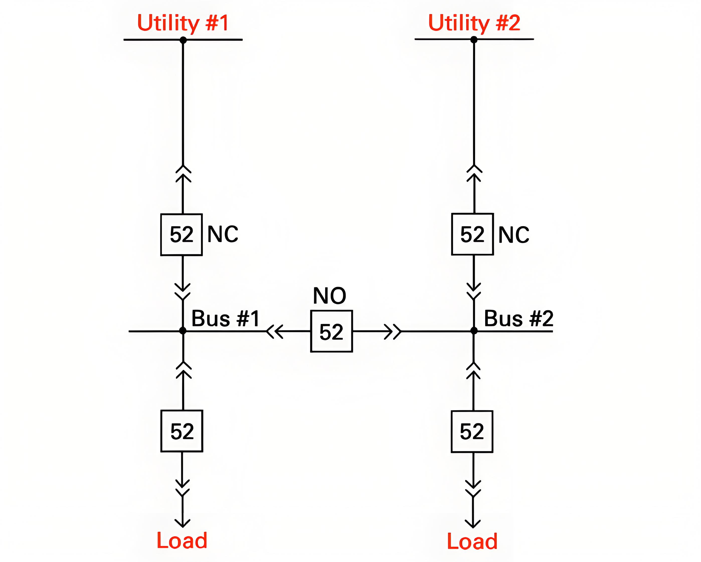
Drop - Pickup Transfers
Drop - pickup transfers, also known as switch - time transfer schemes, can potentially damage motors. If the new source breaker fails to close after the previous source breaker trips open, it may cause a running unit to shut down or an operating process to be interrupted. When a busbar loses power, the connected motors act as generators and supply a residual voltage to the busbar.
This residual voltage typically decays within about one second.
However, drop - pickup transfers occur much faster than one second, and the residual voltage can combine with the voltage from the new source. If the vector sum of these two voltages exceeds 133% of the motor's rated voltage, the transfer can reduce the service life of the motors involved.
Automatic Bus Transfer Schemes
Automatic bus transfer schemes are generally designed to mitigate the stress on motors during transfer and to coordinate with fault relays. Coordination with over - current relaying is accomplished by initiating the transfer after the source circuit breaker trips open. If over - current relays cause the source breaker to trip (indicating a bus fault), the automatic transfer will be blocked.
Moreover, these schemes typically employ residual voltage relays and/or high - speed synchronizing check relays. Transfers are only permitted when the vector sum of the residual voltage and the voltage from the new source is less than 133% of the motor's rated voltage. If the transfer is blocked by 86 lockout relays, the scheme usually times out.
However, if this is not the case, operators should verify that the automatic transfer scheme is deactivated before resetting the bus 86 lockout relays.
Professionalism builds strength. As an expert in the installation and operation of electrical equipment, I am proficient in the installation process and strictly adhere to standards. I skillfully master the operation essentials and can swiftly eliminate faults. With a heart that constantly explores new knowledge, I illuminate the path to the efficient operation of electrical equipment.