Secondary circuit diagram of single-button start and stop
Secondary circuit diagram of single-button start and stop
Physical wiring diagram
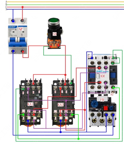
Circuit diagram
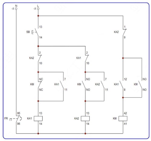
Working Principle:
1. Close QF to connect the power supply. Press SB, and the relay KA1 is energized and pulled in. The normally open contact of KA1 is closed, the coil of the AC contactor KM is energized, KM is pulled in and self-locked. The motor operates.
2. The normally open contact of KM is closed, and the normally closed contact is disconnected. At this time, the coil of the relay KA2 cannot be energized because the normally closed contact of KA1 has been disconnected, so KA2 cannot be pulled in.
3. Release SB. Because KM is self-locked, the AC contactor remains pulled in, and the motor continues to operate. But at this time, KA1 is de-energized and released because SB is released, and its normally closed point is reset to prepare for KA2, which is used when it is necessary to stop the machine.
4. To stop the machine, press the SB button. At this time, the coil of the relay KA1 is cut off by the normally closed point of KM, so KA1 will not be pulled in, while the coil of KA2 is energized and pulled in. Its normally closed point is disconnected to cut off the power supply of the coil of KM. The main contact of KM is disconnected, and the motor stops running.
We aim to gather electrical knowledge and share it with others.
