Voltage Source and Current Source

Edwiin
06/02/2025

Definition of Electrical Source
A source is a device that converts mechanical, chemical, thermal, or other forms of energy into electrical energy. As an active network element, it serves the purpose of generating electrical energy.
In electrical networks, the primary types of sources are voltage sources and current sources:
  • A voltage source is characterized by an electromotive force (emf) as its forcing function.
  • A current source is defined by a current forcing function.

Current and voltage sources are further categorized into ideal sources and practical sources.
Voltage Source
A voltage source is a two-terminal device that maintains a constant voltage at any instant, independent of the current drawn from it. This is referred to as an Ideal Voltage Source, which features zero internal resistance.
In practice, ideal voltage sources do not exist. Sources with inherent internal resistance are called Practical Voltage Sources. This internal resistance causes a voltage drop, reducing the terminal voltage. The smaller the internal resistance (r) of a voltage source, the closer its behavior aligns with an ideal source.
The symbolic representations of ideal and practical voltage sources are as follows:
Figure A shown below shows the circuit diagram and characteristics of an ideal voltage source:
Figure B shown below gives the circuit diagram and characteristics of Practical Voltage Source:
Examples of Voltage Sources
Common examples of voltage sources include batteries and alternators.
Current Source
Current sources are similarly categorized into ideal and practical types.
Ideal Current Source
An ideal current source is a two-terminal circuit element that delivers a constant current to any load resistance connected across its terminals. Notably, the current supplied remains independent of the voltage across the source terminals, and it exhibits infinite internal resistance.
Practical Current Source
A practical current source is modeled as an ideal current source in parallel with a resistance. This parallel resistance accounts for real-world limitations, such as current leakage or internal losses. The symbolic representations are as follows:
Figure C shown below, show its characteristics.

Figure D shown below shows the characteristics of Practical Current Source.

The example of current sources is photoelectric cells, collector currents of transistors.

Edwiin

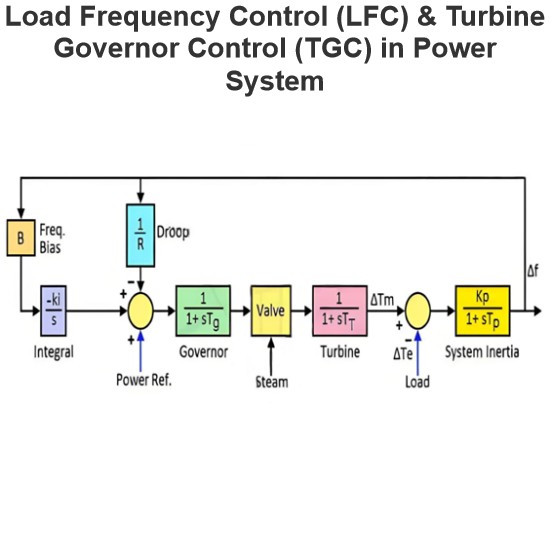
Load Frequency Control (LFC) & Turbine Governor Control (TGC) in Power System
Brief Introduction to Thermal Generating UnitsElectricity generation relies on both renewable and non - renewable energy resources. Thermal generating units represent a conventional approach to power production. In these units, fuels such as coal, nuclear energy, natural gas, biofuel, and biogas are combusted within a boiler.The boiler of a generating unit is an extremely complex system. In its simplest conception, it can be visualized as a chamber whose walls are lined with pipes, through which
Edwiin
06/06/2025
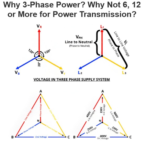
Why 3-Phase Power? Why Not 6, 12 or More for Power Transmission?
It is well-known that single-phase and three-phase systems are the most prevalent configurations for power transmission, distribution, and end-use applications. While both serve as fundamental power supply frameworks, three-phase systems offer distinct advantages over their single-phase counterparts.Notably, multi-phase systems (such as 6-phase, 12-phase, etc.) find specific applications in power electronics—particularly in rectifier circuits and variable frequency drives (VFDs)—wher
Edwiin
06/05/2025
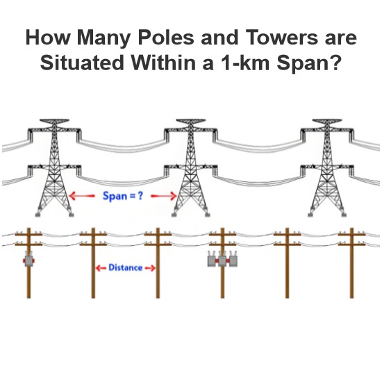
How Many Poles and Towers are Situated Within a 1-km Span?
The number of distribution poles and transmission towers within a 1-kilometer stretch of overhead lines varies significantly based on multiple factors, including voltage level, power line type, supporting structure, geographical location, local regulations, and specific grid requirements.In urban areas, distribution utility poles are typically positioned at closer intervals, while in rural regions, they are spaced farther apart. Additionally, the use of taller structures for higher-voltage trans
Edwiin
06/05/2025
Synchronizing Power and Torque Coefficient
Definition of Synchronizing PowerSynchronizing power, denoted as Psyn, is defined as the variation in synchronous powerP with respect to changes in the load angle δ. Also referred to as thestiffness of coupling,stability factor, orrigidity factor, it quantifies a synchronous machine’s (generator or motor) inherent tendency to maintain synchronism when connected to infinite busbars.Principle of Synchronism MaintenanceConsider a synchronous generator transmitting a steady power Pa at a
Edwiin
06/04/2025
Inquiry
Download
Experts Electrical is dedicated to serving the personnel in the global power industry.
Join Experts Electrical, not only can you discover power equipment and power knowledge, but also canhnd like - minded friends!