Chopper Control of Separately Excited DC Motor
A chopper is a device that converts a fixed direct - current (DC) voltage into a variable DC voltage. Self - commutated devices, such as Metal - Oxide - Semiconductor Field - Effect Transistors (MOSFETs), Insulated - Gate Bipolar Transistors (IGBTs), power transistors, Gate - Turn - Off Thyristors (GTOs), and Integrated Gate - Commutated Thyristors (IGCTs), are commonly used in the construction of choppers. These devices can be turned on or off directly via a gate control signal using low - power inputs and do not require an additional commutation circuit, making them highly efficient and practical for chopper applications.
Choppers are typically operated at high frequencies. This high - frequency operation significantly enhances motor performance by reducing voltage and current ripples and eliminating discontinuous conduction. One of the most notable advantages of chopper control is its ability to enable regenerative braking even at very low rotational speeds. This feature is particularly valuable when the drive system is supplied with a fixed - to - low DC voltage source, allowing for efficient energy recovery during braking operations.
Motoring Control
The figure below illustrates a separately - excited DC motor controlled by a transistor chopper. The transistor Tr is periodically switched with a period Tr, remaining in the conducting state for a duration Ton. The corresponding waveforms of the motor terminal voltage and armature current are also depicted in the figure. When the transistor is on, the motor terminal voltage is V, and the operation of the motor can be described as follows:
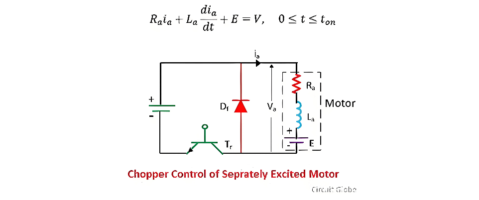
During this specific time interval, the armature current increases from ia1 to ia2. This phase is referred to as the duty interval, as the motor is directly linked to the power source during this period. The direct connection allows electrical energy from the source to be transferred to the motor, enabling it to generate mechanical torque and rotate.
When t = ton), the transistor Tr is deactivated. Subsequently, the motor current begins to freewheel through the diode Df. As a result, the voltage at the motor terminals drops to zero within the time interval ton≤t≤T. This interval is known as the freewheeling interval. During this freewheeling phase, the energy stored in the motor's magnetic field and inductance is dissipated through the freewheeling diode, maintaining the flow of current in a closed loop. The motor's operation during this interval can be further analyzed and described by examining the electrical and magnetic interactions within the circuit components.

Motor current decreases from ia2 to ia1 during this interval.The ratio of duty interval ton to chopper period T is called duty cycle.

Regenerative Braking
The figure below illustrates a chopper configured for regenerative braking operation. The transistor Tr is cyclically switched with a period T and an on - period ton. Depicted alongside is the waveform of the motor terminal voltage va and the armature current ia under continuous conduction conditions. To enhance the inductance value La, an external inductor is incorporated into the circuit.
When the transistor Tr is turned on, the armature current ia rises from ia1 to ia2. This increase in current occurs as electrical energy is temporarily stored in the inductor and the motor's magnetic field, setting the stage for the subsequent energy conversion process that is characteristic of regenerative braking.
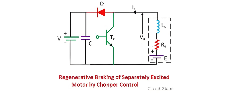
When the motor operates in the regenerative braking mode, it functions as a generator, converting mechanical energy into electrical energy. A portion of this electrical energy contributes to increasing the magnetic energy stored within the inductance of the armature circuit. Meanwhile, the remaining electrical energy is dissipated as heat within the armature windings and the transistors, due to the inherent resistance of these components.

When the transistor is switched off, the armature current traverses through diode D and the power source V, decreasing from ia2 to ia1. In this process, both the electromagnetic energy stored in the circuit and the energy generated by the machine are fed back to the power source. The time interval from 0 to ton is defined as the energy storage interval, during which energy accumulates in the system. Conversely, the interval from ton to T is referred to as the duty interval, when energy transfer and system operation occur.
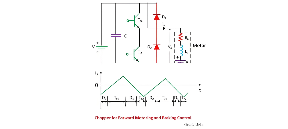
Motoring and Braking Operation Control
During the motoring operation, the transistor Tr1 is regulated to supply power to the motor, enabling it to rotate forward. Conversely, for the braking operation, the transistor Tr2 takes over control. The transition of control from Tr1 to Tr2 seamlessly switches the system's operation from motoring to braking, and reversing this control transfer shifts it back to the motoring state. This precise control mechanism ensures efficient and reliable operation of the electrical drive system under different working conditions.
Dynamic Control
The dynamic braking circuit, along with its corresponding waveform, is depicted in the figure below. In the time interval from 0 to Ton, the armature current ia steadily rises from ia1 to ia2. During this phase, a portion of the electrical energy is stored in the inductance, serving as a reservoir for subsequent operations. Simultaneously, the remaining energy is dissipated as heat within the armature resistance Ra and the transistor TR, a necessary consequence of the electrical resistance present in these components.
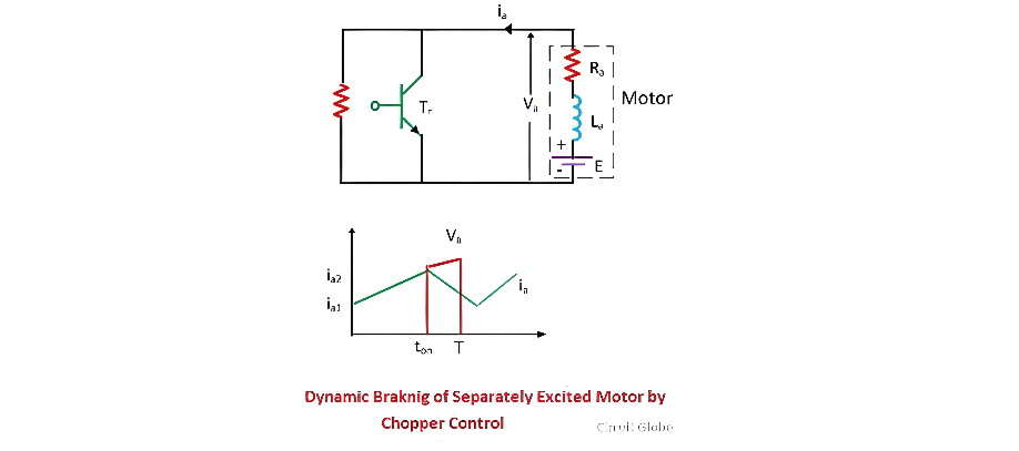
During the time interval Ton ≤ t ≤T the armature current ia drops from ia2 to ia1. In this phase, both the energy generated by the motor and the energy stored in the inductances are dissipated across the braking resistance RB, the armature resistance Ra, and the diode D. The transistor Tr plays a pivotal role in regulating the amount of energy dissipated in RB. By precisely controlling the operation of Tr, one can effectively modulate the power dissipated in RB, thereby influencing the overall braking performance and the effective value of the dissipated energy. This control mechanism allows for fine - tuning of the dynamic braking process, ensuring optimal energy management and system stability.
The Electricity Encyclopedia is dedicated to accelerating the dissemination and application of electricity knowledge and adding impetus to the development and innovation of the electricity industry.

