What is the method for calculating power factor when there is a phase difference between voltage and current?
Definition and Calculation Method of Power Factor
Power Factor (PF) is a crucial parameter that measures the phase difference between voltage and current in an AC circuit. It represents the ratio of actual consumed active power to apparent power, reflecting the efficiency of electrical energy utilization. When there is a phase difference between voltage and current, the power factor is typically less than 1.
1. Definition of Power Factor
The power factor is defined as:

Active Power (P): The actual power consumed, measured in watts (W), representing the portion of power that performs useful work.
Apparent Power (S): The product of voltage and current, measured in volt-amperes (VA), representing the total electrical energy flow in the circuit.
Reactive Power (Q): The component of power that does not consume energy but participates in energy exchange, measured in volt-amperes reactive (VAR).
2. Relationship Between Phase Difference and Power Factor
In purely resistive loads, voltage and current are in phase, resulting in a power factor of 1. However, in inductive loads (such as motors and transformers) or capacitive loads (such as capacitors), there is a phase difference between voltage and current, leading to a power factor less than 1.
The power factor can be expressed using the phase angle ( ϕ) between voltage and current:

Where:
ϕ is the phase angle between voltage and current, measured in radians or degrees.
cos(ϕ) is the cosine of the phase angle, representing the power factor.
3. Power Triangle
To better understand the power factor, the power triangle can be used to illustrate the relationship between active power, reactive power, and apparent power:
Active Power (P): The horizontal side, representing the actual consumed power.
Reactive Power (Q): The vertical side, representing the non-consuming but energy-exchanging component.
Apparent Power (S): The hypotenuse, representing the product of voltage and current.
According to the Pythagorean theorem, the relationship among these three quantities is:

Therefore, the power factor can also be expressed as:

4. Calculation Formula for Power Factor
When the voltage V, current I, and their phase difference ϕ are known, the power factor can be calculated using the following formula:
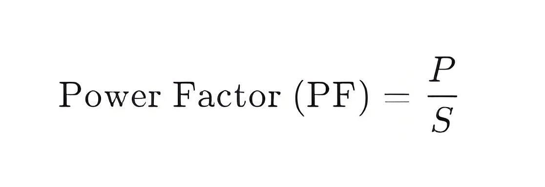
If the active power P and apparent power S are known, the power factor can be directly calculated using:
5. Power Factor Correction
In practical applications, a low power factor increases losses in the power system and reduces its efficiency. To improve the power factor, common methods include:
Installing Parallel Capacitors: For inductive loads, installing parallel capacitors can compensate for reactive power, reduce the phase difference, and thus increase the power factor.
Using Power Factor Correction Devices: Modern equipment often includes automatic power factor correction devices that dynamically adjust reactive power to maintain a high power factor.
Summary
When there is a phase difference between voltage and current, the power factor can be calculated as follows:
Power Factor (PF) = cos(ϕ), where ϕ is the phase angle between voltage and current.
Power Factor (PF) = P/S , where P is the active power and S is the apparent power.
The power factor reflects the efficiency of electrical energy utilization, with an ideal power factor of 1, indicating that voltage and current are perfectly in phase. By implementing appropriate measures (such as installing capacitors or using power factor correction devices), the power factor can be improved, reducing system losses and enhancing overall efficiency.
The Electricity Encyclopedia is dedicated to accelerating the dissemination and application of electricity knowledge and adding impetus to the development and innovation of the electricity industry.
