What are the significances of form and peak factors?
Significance of Form Factor and Crest Factor
Form Factor (FF) and Crest Factor (CF) are two key parameters used to describe the characteristics of alternating current (AC) signals. They are widely applied in power systems, audio processing, communication systems, and other fields. These parameters play a crucial role in evaluating signal quality, device performance, and system design.
1. Form Factor (FF)
Definition:
The form factor is the ratio of the root mean square (RMS) value of an AC signal to its average absolute value (AVG). The formula is:
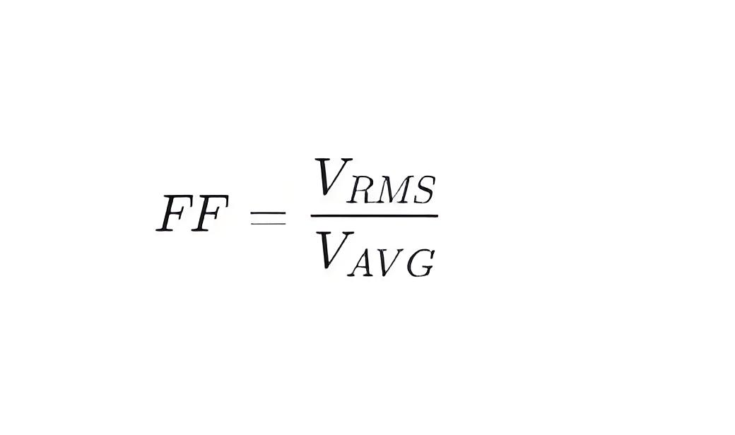
Where:
VRMS is the RMS value of the signal, representing its effective value.
VAVG is the average absolute value of the signal, representing its average amplitude.
Significance:
Assessing Signal Shape: The form factor reflects the shape of the signal waveform. For a pure sine wave, the form factor is 1.11. If the signal contains harmonics or non-sinusoidal components, the form factor will deviate from this value. Therefore, the form factor can help identify whether the signal is a pure sine wave or if there is distortion or deformation.
Application in Power Systems: In power systems, the form factor is used to evaluate the quality of grid voltage and current. A high form factor may indicate harmonic pollution, which can affect the efficiency and lifespan of electrical equipment. For example, transformers and motors may generate additional heat under non-sinusoidal conditions, leading to overheating and failure.
Electronic Device Design: In designing power supplies, filters, and other electronic devices, the form factor is an important consideration. It helps engineers select appropriate components to ensure that the devices can handle non-sinusoidal inputs without damage.
Typical Values:
Sine Wave: 1.11
Square Wave: 1.00
Triangle Wave: 1.15
Waveform with Harmonics: Greater than 1.11
2. Crest Factor (CF)
Definition:
The crest factor is the ratio of the peak value of an AC signal to its RMS value. The formula is:
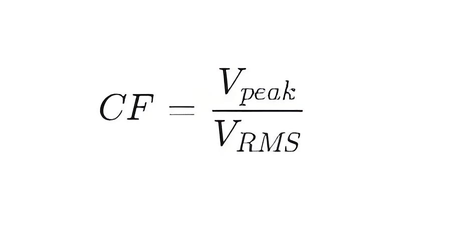
Where:
Vpeak is the maximum amplitude of the signal.
VRMS is the RMS value of the signal.
Significance:
Assessing Peak Characteristics: The crest factor reflects the relationship between the peak and RMS values of the signal. For a pure sine wave, the crest factor is 1.414. If the signal contains spikes or pulse components, the crest factor will significantly increase. Therefore, the crest factor can help identify whether there are instantaneous large currents or voltage peaks in the signal, which is crucial for protecting devices from overload or short circuits.
Application in Power Systems: In power systems, the crest factor is used to evaluate the peak characteristics of current and voltage. A high crest factor may indicate instantaneous large currents or voltage peaks, which can place higher demands on protective devices such as circuit breakers and fuses. For example, during motor startup, large starting currents can cause the crest factor to rise, requiring protective devices that can withstand these transient currents.
Application in Audio Processing: In audio processing, the crest factor is used to assess the dynamic range of audio signals. A high crest factor means that the audio signal contains significant instantaneous peaks, which can lead to overloading speakers or other audio equipment, causing distortion or damage. Therefore, audio engineers often use compressors or limiters to control the crest factor, ensuring that the audio signal does not exceed the equipment's handling capacity.
Application in Communication Systems: In communication systems, the crest factor is used to evaluate the characteristics of modulated signals. A high crest factor can cause power amplifiers (PAs) to operate in nonlinear regions, leading to distortion and spectral regrowth, which can degrade communication quality. Therefore, communication system designers typically optimize modulation schemes to reduce the crest factor, ensuring stable and reliable signal transmission.
Typical Values:
Sine Wave: 1.414
Square Wave: 1.00
Triangle Wave: 1.73
Pulse Wave: Much greater than 1.414
Joint Application of Form Factor and Crest Factor
Harmonic Analysis in Power Systems: The form factor and crest factor can be used together to analyze harmonic pollution in power systems. The form factor reflects the overall shape of the signal, while the crest factor focuses on the instantaneous peaks. By combining these two parameters, a more comprehensive evaluation of power quality can be made, and appropriate measures can be taken to improve it.
Device Selection and Protection: When selecting power equipment (such as transformers, circuit breakers, fuses, etc.), the form factor and crest factor are important reference indicators. High form factors and crest factors can impose greater stress on equipment, so devices that can withstand this stress must be chosen. Additionally, protective devices (such as overcurrent protection, overvoltage protection, etc.) need to be designed based on the crest factor to ensure they can respond promptly to instantaneous large currents or voltage peaks, protecting the system's safety.
Signal Processing in Audio and Communication Systems: In audio and communication systems, the form factor and crest factor are used to evaluate the dynamic characteristics and modulation characteristics of signals. By optimizing signal processing algorithms (such as compression, limiting, modulation, etc.), the form factor and crest factor can be effectively controlled, ensuring high-quality and stable signal transmission.
Summary
The form factor and crest factor are two important parameters for assessing the characteristics of AC signals, with wide applications in power systems, audio processing, communication systems, and other fields. Their significance lies in:
Form Factor (FF): The ratio of the RMS value to the average absolute value, reflecting the shape of the signal. It is used for power quality assessment and device selection.
Crest Factor (CF): The ratio of the peak value to the RMS value, reflecting the peak characteristics of the signal. It is used for protective device design and signal processing.
By properly using the form factor and crest factor, engineers and technicians can better understand signal characteristics, optimize system design, and ensure the safe and efficient operation of equipment.
The Electricity Encyclopedia is dedicated to accelerating the dissemination and application of electricity knowledge and adding impetus to the development and innovation of the electricity industry.
