How does a magnet affect an electron moving through a wire and producing an electrical current?
How Do Magnets Affect the Movement of Electrons in a Wire and Generate Current?
Magnets can influence the movement of electrons in a wire and generate current through several mechanisms, primarily based on Faraday's law of electromagnetic induction and the Lorentz force. Here is a detailed explanation:
1. Faraday's Law of Electromagnetic Induction
Faraday's law of electromagnetic induction states that when the magnetic flux through a closed loop changes, an electromotive force (EMF) is induced in the loop, which can cause a current to flow. Specifically:
Changing Magnetic Field: When a magnet moves near a wire or when a wire moves in a magnetic field, the magnetic flux through the wire loop changes.
Induced EMF: According to Faraday's law, the change in magnetic flux induces an EMF E, given by the formula:
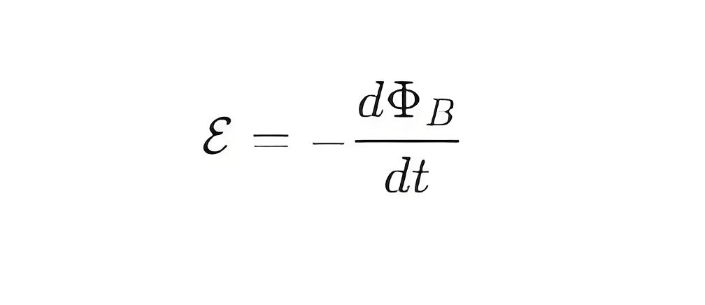
where ΦB is the magnetic flux and t is time.
Current: The induced EMF causes electrons to move in the wire, creating a current I. If the wire forms a closed loop, the current will continue to flow.
2. Lorentz Force
The Lorentz force describes the force experienced by a charged particle in a magnetic field. When electrons move in a wire, they experience the Lorentz force if a magnetic field is present. Specifically:
Lorentz Force Formula: The Lorentz force F is given by:
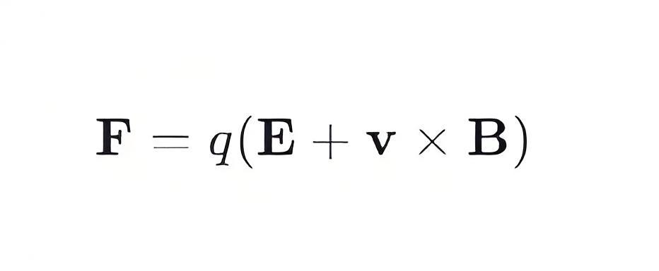
where q is the charge, E is the electric field, v is the velocity of the charge, and B is the magnetic field.
Electron Motion in a Magnetic Field**: When electrons move in a magnetic field, the Lorentz force F=qv×B causes the electrons to deflect. This deflection changes the path of the electrons, affecting the direction and magnitude of the current.
3. Specific Applications
Generators
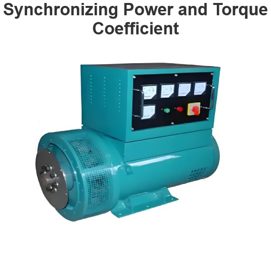
Principle: Generators utilize Faraday's law of electromagnetic induction by rotating magnets or wires to produce changing magnetic flux, which induces an EMF and current in the wires.
Application: Generators in power stations use large rotating magnets and wire coils to produce large-scale currents.
Motors
Principle: Motors use the Lorentz force to convert electrical energy into mechanical energy. When current flows through a wire in a magnetic field, the wire experiences a force that causes it to rotate.
Application: Motors are widely used in various mechanical devices, such as household appliances, industrial equipment, and vehicles.
Transformers
Principle: Transformers use Faraday's law of electromagnetic induction to transfer energy between primary and secondary coils through a changing magnetic field, thereby altering the voltage and current.
Application: Transformers are used in power transmission and distribution systems to step up or step down voltages.
4. Experimental Example
Faraday Disk Experiment
Setup: A metal disk is fixed on an axle, which is connected to a galvanometer. The metal disk is placed in a strong magnetic field.
Process: When the metal disk rotates, the magnetic flux through the disk changes, inducing an EMF according to Faraday's law, which causes a current to flow through the axle and the galvanometer.
Observation: The galvanometer shows a current flowing, demonstrating that the changing magnetic flux has generated an EMF.
Summary
Magnets affect the movement of electrons in a wire and generate current through Faraday's law of electromagnetic induction and the Lorentz force. A changing magnetic field induces an EMF in the wire, causing electrons to move and form a current. The Lorentz force deflects the path of moving electrons in a magnetic field, influencing the direction and magnitude of the current. These principles are widely applied in generators, motors, and transformers.
The Electricity Encyclopedia is dedicated to accelerating the dissemination and application of electricity knowledge and adding impetus to the development and innovation of the electricity industry.
