Voltage Regulators: Linear, Shunt, and Zener Diode
What is Voltage Regulation
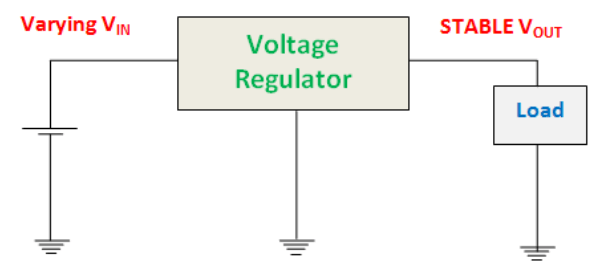
A voltage regulator is an electronic or electrical device that can sustain the voltage of power supply within suitable limits. The electrical equipment connected to the voltage source should bear the value of the voltage. The source voltage should be in a certain range which is acceptable for the connected pieces of equipment. This purpose is fulfilled by implementing a voltage regulator.
A voltage regulator – as the same suggests – regulates the voltage, regardless of the adjustments in the input voltage or connected load. It works as a shield for protective devices from damage. It can regulate both AC or DC voltages, depending on its design.
Types of Voltage Regulators
There are two main types of voltage regulators available:
Linear Voltage Regulators
Switching Voltage Regulators
These can be further classified into more specific voltage regulators, as discussed below.
Linear Voltage Regulator
This type of voltage regulator performs as a voltage divider. It employs FET in Ohmic region. The steady output is sustained by varying the resistance of voltage regulator with respect to the load. Generally, these types of voltage regulator are of two types:
Series voltage regulator
Shunt voltage regulator
Series Voltage Regulator
It implements a variable element positioned in series with the connected load. The steady output is sustained by varying the resistance of this element with respect to the load. They are of two types that are briefed below.
Discrete Transistor Series Voltage Regulator
Here from the block diagram, we can see an unregulated input is first fed into a controller. It actually controls the input voltage magnitude and given to the output. This output is given to the feedback circuit. It is sampled by the sampling circuit and given to the comparator. There it is compared by the reference voltage and given back to the output.
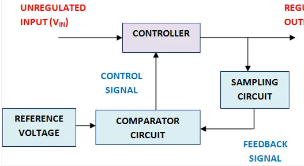
Here, the comparator circuit will give a control signal to the controller whenever there is an increase or decrease in the output voltage. Thus, the controller will reduce or increase the voltage to the acceptable range so that a sustained voltage will get as the output.
Zener Diode as Voltage Regulator
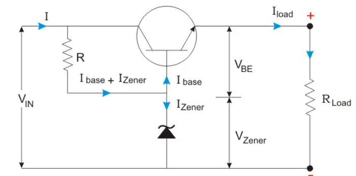
When a Zener diode is used as a voltage regulator, it is known as a Zener controlled transistor series voltage regulator or an emitter follower voltage regulator. Here, the transistor used is emitter follower (see figure below). The emitter and the collector terminals of the series pass transistor used here are in series with respect to load. The variable element is a transistor and the Zener diode will supply the reference voltage.

Shunt Voltage Regulator
The shunt voltage regulator provides a way from the supply voltage reaching to the ground with the help of variable resistance. From the load, the current is shunted away from the load to the ground. We can simply say that this regulator can absorb current and it is less efficient compared to the series voltage regulator. The applications include error amplifiers, voltage monitoring, precision current limiters, etc. They are of two types that are briefed below.
Discrete Transistor Shunt Voltage Regulator
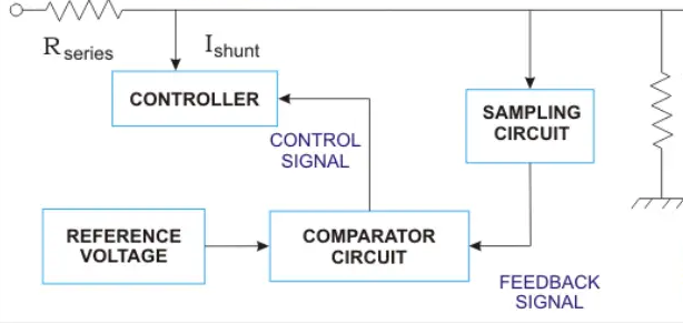
Here, the current is shunted away from the load. The controller will shunt a portion of the total current that is developed by the unregulated input which is given to the load. The voltage regulation takes place across the load.
Here, the comparator circuit will give a control signal to the controller whenever there is an increase or decrease in the output voltage because of the variation in load. Thus, the controller will shunt the extra current from the load so as to get a sustained voltage as the output.
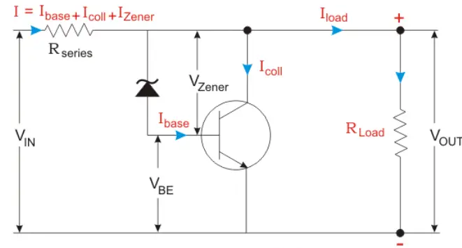
Zener Controlled Transistor Shunt Voltage Regulator
Here, the unregulated voltage is directly proportional to the voltage drop occurs in the series resistance. This voltage drop is related to the current given to the load. The output voltage is related to the transistor base emitter voltage (VBE) and the Zener diode.

| Advantages of Linear Voltage Regulator | Disadvantages of Linear Voltage Regulator |
| Design is very simple | Low efficiency |
| Less output ripple | Space requirement is large |
| Response time is fast | Voltage cannot be increased |
| Less noise | A heat sink is sometimes required |
Switching Voltage Regulator
This regulator quickly switches a device in series to on and off. Like the linear regulators, a feedback mechanism is incorporated here to control the quantity of charge carried to the load. This quantity is set as the duty cycle of the switch. The output voltage can be greater or the polarity of output can be opposite that of the input by using this voltage regulator.
This is a highly efficient voltage regulator. Three different types are step-up voltage regulator, buck voltage regulator, and boost/buck voltage regulator. The most simplified circuit diagram of a switching voltage regulator is shown below.

| Advantages of Switching Voltage Regulator | Disadvantages of Switching Voltage Regulator |
| Efficiency is very high. | Complex design |
| Size and weight are very low. | Expensive |
| Boost or buck or inverting or buck/boost is possible. | Noise is high |
| Less noise | Transient recovery time is time-consuming |
Application of Voltage Regulators
The applications for voltage regulators include:
Power distribution system
Automobile alternator
Power station generator plant
Computer power supplies
Source: Electrical4u.
Statement: Respect the original, good articles worth sharing, if there is infringement please contact delete.
Electrical4U is dedicated to the teaching and sharing of all things related to electrical and electronics engineering.

