Pull Down Resistor: What is it?
What is a Pull-Down Resistor?
A pull-down resistor is used in electronic logic circuits to ensure a known state for a signal. It is usually used in combination with transistors and switches to ensure the voltage between ground and Vcc is actively controlled when the switch is open (similar to a pull-up resistor).
This can sound confusing at first, so let’s go into an example.
A digital circuit has three input logic states; High (1), Low (0), and floating (undefined). But the digital circuit only operates in high or low states.
In a floating state, the digital circuits may confuse between high and low. The resisters are used to limit the current in a circuit.
Consider a digital circuit operating on 5 V. If the input voltage is between 2 to 5 V, the input logic of the circuit is high. And if the input voltage is less than 0.8 V, the input logic is low.
When the input voltage is between 0.9 to 1.9 V, the circuit will be confused to select a state.
Pull-down or pull-up resistors are used in digital circuits to avoid this situation. In a floating state, the pull-down resisters hold the logic level near zero volts when no active connection is available with a circuit.
How Does a Pull-Down Resistor Work?
A pull-down resistor is connected to the ground, as shown in the figure below.
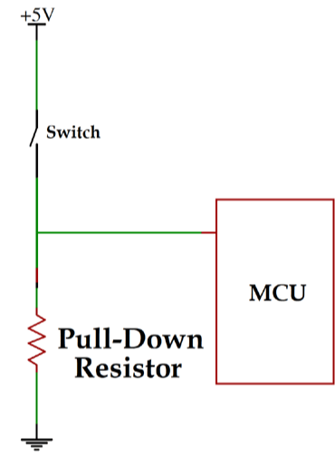
Pull Down Resistor Working
When a mechanical switch is open, the input voltage is pulled down to zero (low). And digital pin ensures low state.
When a mechanical switch is closed, the input voltage is pulled up to high. In this condition, the digital pin ensures high logic level.
The resistance of a pull-down resistor must be higher than the impedance of a circuit. Otherwise, it cannot pull down current, and some voltage may be appearing at the input pin.
The circuit may operate in a floating state in this condition, whether the switch is open or closde.
Calculation of Pull-Down Resistors
The resistance required for pull-down resistors is calculated by Ohm’s law.
The formula to calculate the pull-down resistance is;
Where,
VLmax is a maximum required voltage in a low state,
Isource is a gate-source current.
For Example, minimum voltage required to turn off circuit is 0.8 V. And gate source current is 0.5 mA.
In this condition, we can choose the maximum pull-down resistance is 1.6 kΩ. However, we cannot use more than this resistance.
Because significant resistance creates more voltage drop, it results in gate input voltage beyond the normal low voltage range.
Hence, choose a pull-down resistor at a voltage drop of 0.4-0.5 V. Then select the pull-down resistance value below its maximum value.
Pull Down vs. Pull Up Resistor
The difference between pull-down and pull-up resistors is as shown in the table below.
| Pull-down Resistor | Pull-up Resistor | |
| Input Stability | It is used to ensure an input terminal is stable at a low level. | It is used to ensure an input terminal is stable at a high level. |
| Connection | One terminal is connected with the ground. | One terminal is connected with VCC. |
| When a switch is open | Current path is input to ground. Voltage at an input pin is Low. | Current path is VCC to an input pin. Voltage at input pin is high. |
| When a switch is close | Current path is VCC to an input pin. Voltage at input pin is high. | Current path is VCC to input pin to ground. Voltage at input pin is low. |
| Used | Rarely used | More commonly used |
| Formula |
Applications of Pull-Down Resistors
Applications of pull-down resisters are listed below.
Pull-down resistors are frequently used in digital circuits (like microcontrollers) to ensure the logic level. Most of the microcontrollers are used inbuilt programmable pull-down resistors.
It is used in the I2C protocol bus.
It is used in Analog-digital converters to provide a controlled flow of current.
Source: Electrical4u.
Statement: Respect the original, good articles worth sharing, if there is infringement please contact delete.
Electrical4U is dedicated to the teaching and sharing of all things related to electrical and electronics engineering.
