Ohm’s Law: How it Works (Formula and Ohm’s Law Triangle)
What is Ohm’s Law?
Ohm’s law states that the electrical current flowing through any conductor is directly proportional to the potential difference (voltage) between its ends, assuming the physical conditions of the conductor do not change.
In other words, the ratio of potential difference between any two points of a conductor to the current flowing between them is constant, provided the physical conditions (e.g., temperature etc.) do not change.
Mathematically, Ohm’s law can be expressed as,
Introducing the constant of proportionality, the resistance R in the above equation, we get,
Where,
R is the resistance of the conductor in Ohm (
 ),
),I is the current through the conductor in Amperes (A),
V is the voltage or potential difference measured across the conductor in Volts (V).
Ohm’s law is applicable to both DC and AC.
The relationship between the potential difference or voltage (V), the current (I) and the resistance (R) in an electrical circuit was first discovered by the German physicist George Simon Ohm.
The unit of resistance is Ohm (![]() ) was named in honour of George Simon Ohm.
) was named in honour of George Simon Ohm.
How Does Ohm’s Law Work?
As per the definition of Ohm’s law, the current flowing through a conductor or resistor between two points is directly proportional to the difference in voltage (or potential difference) across the conductor or resistor.
But… that can be a bit difficult to understand.
So let’s get a better intuitive sense for Ohm’s Law by using some analogies.
Analogy 1
Consider a water tank placed at a certain height above the ground. There is a hose at the bottom of the water tank as shown in the image below.
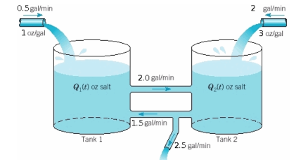
The water pressure in pascals at the end of the hose is analogous to voltage or potential difference in an electric circuit.
The water flow rate in litres per second is analogous to electric current in coulombs per second in an electric circuit.
The restrictors to the water flow such as apertures placed in pipes between two points are analogues to the resistors in an electric circuit.
Thus, the water flow rate through an aperture restrictor is proportional to the difference in water pressure across the restrictor.
Similarly, in an electric circuit, the current flowing through a conductor or resistor between two points is directly proportional to the difference in voltage or potential difference across the conductor or resistor.
We can also say that resistance offered to water flow is depending on the length of the pipe, the material of the pipe, and the height of the tank placed above the ground.
Ohm’s work in a similar manner in an electric circuit that electrical resistance offered to the current flow is depending on the length of the conductor and material of the conductor used.
Analogy 2
A simple analogy between the hydraulic water circuit and the electric circuit to describe how Ohm’s law work is shown in the image below.
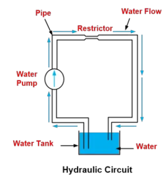
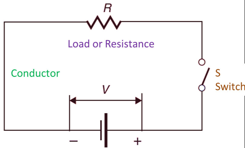
As shown, if water pressure is constant and the restriction increases (making it more difficult for the water to flow), then the rate of water flow decreases.
Similarly, in an electric circuit, if voltage or potential difference is constant and the resistance increases (making it more difficult for the current to flow), then the rate of flow electric charge i.e., current decreases.

Now, if the restriction to water flow is constant and the pump pressure increases, the rate of water flow increases.
Similarly, in an electric circuit, if resistance is constant and the potential difference or voltage increases, then the rate of flow of electric charge i.e., current increases.

Ohm’s Law Formula
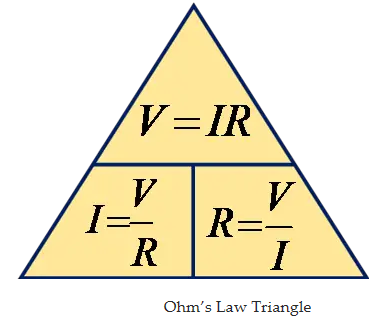
The relationship between voltage or potential difference, current and resistance can be written in three different ways.
If we know any two values, we can calculate the third unknown value by using ohm’s law relationship. Thus, ohm’s law is very useful in electronics and electrical formulas and calculations.
When known electric current flows through known resistance then the voltage drop across the resistance can be calculated by the relationship
When a known voltage is applied across known resistance then the current flowing through the resistance can be calculated by the relationship
When a known voltage is applied across an unknown resistance and the current flowing through the resistance is also known then the value of unknown resistance can be calculated by the relationship
Ohm’s Law Formula for Power
The power transferred is the product of supply voltage and electric current.
1)
Now, Put  in equation (1) we get,
This formula is known as the ohmic loss formula or resistive heating formula.
Now, put ![]() in equation (1) we get,
in equation (1) we get,
From the above relationship, we can determine power dissipation in resistance if either voltage and resistance or current and resistance are known.
We can also determine the unknown resistance value by using the above relationship if either voltage or current is known.
If any two variables of power, voltage, current and resistance are known then by using Ohm’s law we can determine the other two variables.
The Limitations of Ohm’s Law
Some limitations of Ohm’s law are discussed below.
Ohm’s law does not apply to all non-metallic conductors. For example, for silicon carbide, the relationship is given by
 where K and m are constants and m<1.
Ohm’s Law is not applicable to the following Non-Linear elements.
Resistance
Semiconductors
Vacuum tubes
Electrolytes
(Note that Non-linear elements are those in which the relation between current and voltage is nonlinear i.e., the current is not exactly proportional to the applied voltage.)
Ohm’s law is applicable to metal conductors at a constant temperature only. If the temperature changes, the law is not applicable.
Ohm’s law is also not applicable to unilateral networks. Note that a unilateral network contains unilateral elements such as transistors, diodes, etc. Unilateral elements are those elements that allow the flow of current only in one direction.
Ohm’s Law Triangle
The basic formulas for ohm’s law are summarised below ohm’s law triangle.
Ohm’s Law Practice Problems
Example 1
As shown in the circuit below, a current of 4 A is flowing through the resistance of 15 Ω. Determine the voltage drop across the circuit using ohm’s law.
Solution:
Given Data: ![]() and
and ![]()
According’s to ohm’s law,
Thus, by using ohm’s law equation, we get the voltage drop across the circuit 60 V.
Example 2
As shown in the circuit below, a supply voltage of 24 V is applied across the resistance of 12 Ω. Determine the current flowing through the resistor using ohm’s law.
![]()
Solution:
Given Data: ![]() and
and ![]()
According’s to ohm’s law,
Thus, by using ohm’s law equation, we get the current flowing through the resistor is 2 A.
Example 3
As shown in the circuit below, a supply voltage is 24 V and the current flowing through unknown resistance is 2 A. Determine the unknown value of resistance using ohm’s law.
Solution:
Given Data: ![]() and
and ![]()
According’s to ohm’s law,
Thus, by using ohm’s law equation, we get the unknown resistance value ![]() .
.
Applications of Ohm’s Law
Some of the applications of Ohm’s law includes:
To calculate the unknown potential difference or voltage, resistance, and flow of the current of an electric circuit.
Ohm’s law is used in an electronic circuit to determine the internal voltage drop across the electronic components.
Ohm’s law is used in DC measuring circuits particularly in DC ammeter in which a low resistance shunt is used to divert the current.
Source: Electrical4u
Statement: Respect the original, good articles worth sharing, if there is infringement please contact delete.
Electrical4U is dedicated to the teaching and sharing of all things related to electrical and electronics engineering.


