What is Ionization Energy?
The ability of an element to give away its outermost electrons to form positive ions is manifested in the amount of energy supplied to its atoms sufficiently enough to take away the electrons out of them. This energy is known as Ionisation Energy. Simply speaking, the Ionisation Energy is the energy supplied to an isolated atom or molecule to knockout its most loosely bound valence shell electron to form a positive ion. Its unit is electron-volt eV or kJ/mol and is measured in an electric discharge tube in which a fast-moving electron collides with a gaseous element to eject one of its electrons. The lesser Ionisation Energy (IE), the better the ability to form cations.
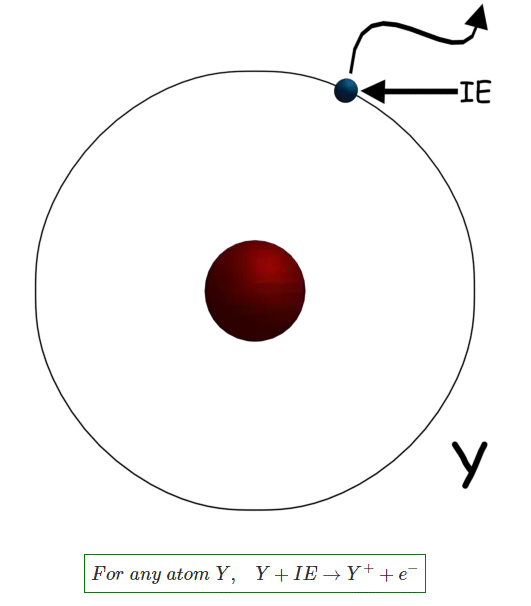
This can be explained with the Bohr model of an atom, in that it considers a hydrogen-like atom in which an electron revolves around a positively charged nucleus due to the columbic force of attraction and the electron can only have fixed or quantized energy levels. The energy of a Bohr model electron is quantized and given as below :
Where, Z is the atomic number and n is the principal quantum number where n is an integer. For a hydrogen atom, Ionisation energy is 13.6eV.
The Ionisation Energy (eV) is the energy required to take the electron from n = 1 (ground state or most stable state) to infinity. Hence taking 0 (eV) reference at infinity, the Ionisation Energy can be written as :
For example, the first ionization energy of Sodium (Na) is given as :
And its second Ionisation Energy is
Hence, IE2 > IE1 (eV). This is also true if there are K number of ionisations, then IE1 < IE2 < IE3……….< IEk
Metals have low Ionisation Energy. Low Ionisation Energy implies better conductivity of the element. For example, the conductivity of Silver (Ag, atomic number Z = 47) is 6.30 × 10⁷ s/m and its Ionisation Energy is 7.575 eV and for Copper (Cu, Z = 29) is 5.76 × 10⁷ s/m and its Ionisation Energy is 7.726 eV. In conductors the low Ionisation Energy causes the electrons to move throughout the positively charged lattice, forming an electron cloud.
Factors Affecting Ionisation Energy
In the periodic table, the general trend is that the Ionisation Energy increases from left to right and decreases from top to bottom. So the factors affecting ionization energy can be summarised below:
Size of the Atom: The Ionisation Energy decreases with the size of the atom because as the atomic radius increases the columbic force of attraction between the nucleus and outermost electron decreases and vice-versa.
Shielding Effect: The presence of inner shell electrons shield or weaken the columbic force of attraction between the nucleus and the valence shell electrons. Hence ionization energy decreases. The number of inner electrons means more shielding. However, in the case of gold, the Ionisation Energy is greater than silver even if the size of gold is more than silver. This is due to the weak shielding offered by the inner d and f orbitals in case of gold.
Nuclear Charge: The more the nuclear charge, the more it will be difficult to ionize the atom due to more attraction force between nucleus and electrons.
Electronic Configuration: The more stable the electronic configuration of the atom, the more difficult is to withdraw an electron hence more Ionisation Energy.
Source: Electrical4u
Statement: Respect the original, good articles worth sharing, if there is infringement please contact delete.
Electrical4U is dedicated to the teaching and sharing of all things related to electrical and electronics engineering.
