Series And Parallel Inductors (Formula & Example Problems)
What is an Inductor?
An inductor (also known as an electrical inductor) is defined as a two-terminal passive electrical element that stores energy in the form of a magnetic field when electric current flows through it. It is also called a coil, chokes, or reactor.
An inductor is simply a coil of wire. It usually consists of a coil of conducting material, typically insulated copper, wrapped into an iron core either of plastic or ferromagnetic material; thus, it is called an iron-core inductor.
Inductors are typically available in the range from 1 µH (10-6 H) to 20 H. Many inductors have a magnetic core made of ferrite or iron inside the coil, which is used to increase the magnetic field and thus the inductor’s inductance.
According’s to Faraday’s law of electromagnetic induction, when an electric current flowing through an inductor or coil changes, the time-varying magnetic field produces an e.m.f (electromotive force) or voltage in it. The induced voltage or e.m.f. across an inductor is directly proportional to the rate of change of the electric current flowing through the inductor.
Inductance (L) is a property of an inductor that opposes any change in magnitude or direction of current flowing through it. The larger an inductor’s inductance, the greater the capacity to store electrical energy in the form of the magnetic field.
How Do Inductors Work?
The inductor in a circuit opposes changes in current flow through it by inducing a voltage across it which is proportional to the rate of change of current flow. To understand how the inductor work in a circuit, consider the image shown below.
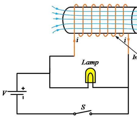
As shown, a lamp, a coil of wire (inductor), and a switch are connected to a battery. If we remove the inductor from the circuit, the lamp lights up normally. With the inductor, the circuit behaves completely differently.
The inductor or coil has much lower resistance compared to the lamp, thus when the switch is closed most of the current should starts flows through the coil as it provides a low-resistance path to the current. hence, we expect that lamp to glow very dimly.
But due to inductor behavior in the circuit, when we close the switch, the lamp glows brightly and then gets dimmer and when we open the switch, the bulb glows very brightly and then quickly goes out.
The reason is that, when voltage or potential difference is applied across an inductor, the electric current flowing through an inductor produces a magnetic field. This magnetic field again creates an induced electric current in the inductor but of opposite polarity, according’s to Lenz’s law.
This induced current due to the magnetic field of the inductor tries to oppose any change, an increase or a decrease, in the current. Once the magnetic field is built, the current can flow normally.
Now, when the switch is closed, the magnetic field around the inductor keeps current flowing in the inductor until the magnetic field collapses. This current keeps the lamp glowing for a certain amount of time even though the switch is open.
In other words, the inductor can store energy in the form of a magnetic field and it tries to oppose any change in the current flowing through it. Thus, the overall result of this is that the current through an inductor cannot change instantaneously.
Inductor Circuit Symbol
The schematic circuit symbol for an inductor is shown in the image below.
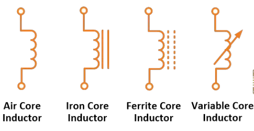
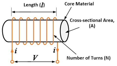
Inductor Equation
Voltage Across an Inductor
The voltage across an inductor is directly proportional to the rate of change of the electric current flowing through the inductor. Mathematically, the voltage across the inductor can be expressed as,
where, ![]() = Instantaneous voltage across the inductor in Volts,
= Instantaneous voltage across the inductor in Volts,
![]() = Inductance in Henry,
= Inductance in Henry,
![]() = Rate of change of electric current in ampere per second
= Rate of change of electric current in ampere per second
The voltage across an inductor is due to the energy stored in the magnetic field of the inductor.
If d.c. current flows through the inductor ![]() becomes zero as d.c. current is constant with respect to time. Hence, the voltage across the inductor becomes zero. Thus, as far as d.c. quantities are considered, in steady-state, the inductor acts as a short circuit.
becomes zero as d.c. current is constant with respect to time. Hence, the voltage across the inductor becomes zero. Thus, as far as d.c. quantities are considered, in steady-state, the inductor acts as a short circuit.
Current Through an Inductor
We can express current through an inductor in terms of voltage developed across it as
In the above equation, the limits of integration are decided by considering past history or initial conditions i.e., form ![]() .
.
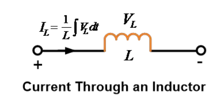
Now, assuming that switching action takes place at t=0, that means the switch is closed at t=0. We have the equation of current through an inductor as,
We can split integration limits into two intervals as ![]() and
and ![]() . we know that
. we know that ![]() is the instant just before switching action takes place, while
is the instant just before switching action takes place, while ![]() is the instant just after switching action takes place. Hence, we can write
is the instant just after switching action takes place. Hence, we can write
Therefore,
Here, the term ![]() indicate the value of inductor current in history period which is nothing but initial condition of
indicate the value of inductor current in history period which is nothing but initial condition of ![]() . Let it be denoted by
. Let it be denoted by ![]() .
.
At ![]() , we can write,
, we can write,
![]()
Initially, we assumed that switching action takes place at zero time. Thus, integration from ![]() to
to ![]() is zero.
is zero.
Therefore,
Thus, the current through the inductor cannot change instantaneously. That means the current through an inductor, before and after switching action is the same.
Inductor at t=0
Inductor at ![]() , i.e., at the time of switching the voltage across the inductor, is ideally
, i.e., at the time of switching the voltage across the inductor, is ideally ![]() as time interval
as time interval ![]() is zero. Thus, at the time switching inductor acts as an open circuit. While in steady-state at
is zero. Thus, at the time switching inductor acts as an open circuit. While in steady-state at ![]() it acts as a short circuit.
it acts as a short circuit.
If the inductor carries an initial current I0 before switching action, then at instant ![]() it acts as a constant current source of value
it acts as a constant current source of value ![]() , while in steady-state at
, while in steady-state at ![]() , it acts as a short circuit across a current source.
, it acts as a short circuit across a current source.
Series and Parallel Inductors
The inductors in series and parallel behave similarly to resistors in series and parallel. Consider two magnetically coupled coils 1 and 2 having self-inductance ![]() and
and ![]() respectively. Let M be the mutual inductance between two coils in henry.
respectively. Let M be the mutual inductance between two coils in henry.
The two inductors in an electrical circuit may be connected in different ways which give different values of equivalent inductance as discussed below.
Inductors in Series Formula
How to add inductors in series
Consider a circuit containing two mutually coupled inductors or coils connected in series. There are two possible ways to connect the inductors in series.
In a first way, the fluxes produced by the inductors act in the same direction. Then, such inductors are said to be connected in series-aiding or cumulatively.
In a second way, if the current is reversed in the other inductor so that the fluxes produced by the inductors oppose each other, then such inductors are said to be connected in series-opposition or differentially.
Let the self-inductance of inductor 1 be ![]() and that of inductor 2 be
and that of inductor 2 be ![]() . Both the inductors are coupled with the mutual inductance M.
. Both the inductors are coupled with the mutual inductance M.
Series-aiding (Cumulative) Connection (mutually induced emf assists the self-induced EMFs)
The two inductors or coils are connected in series-aiding or cumulatively, as shown in the image below.
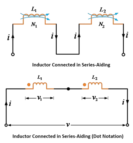
In this connection, the self and mutual fluxes of both the inductors act in the same direction; thus, self and mutually induced e.m.f.s are also in the same direction.
Therefore,
Self-induced e.m.f. in inductor 1,

Mutually induced e.m.f. in inductor 1,

Self-induced e.m.f. in inductor 2,

Mutually induced e.m.f. in inductor 1,

Total induced e.m.f. in the combination,
If ![]() is the equivalent inductance of the two inductors in a series-aiding connection, the e.m.f. induced in the combination is given by,
is the equivalent inductance of the two inductors in a series-aiding connection, the e.m.f. induced in the combination is given by,
Comparing equations (1) and (2), we get,
The above equation gives the equivalent inductance of two cumulatively or additively connected series inductors or coils.
If there is no mutual inductance between the two coils (i.e., M = 0), then,
Series Opposition (Differential) Connection (mutually induced emf opposes the self-induced EM
Consider a circuit containing two mutually coupled inductors or coils connected in series such that the fluxes produced by the two inductors oppose each other, as shown in the image below.
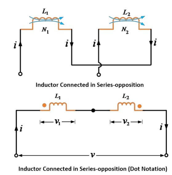
As fluxes are in opposition, the sign for mutual-induced e.m.f. will be opposite to that of self-induced e.m.f.s. Therefore,
Self-induced e.m.f. in inductor 1,

Mutually induced e.m.f. in inductor 1,

Self-induced e.m.f. in inductor 2,

Mutually induced e.m.f. in inductor 1,

Total induced e.m.f. in the combination,
If ![]() is the equivalent inductance of the two inductors in a series opposition connection, the e.m.f. induced in the combination is given by,
is the equivalent inductance of the two inductors in a series opposition connection, the e.m.f. induced in the combination is given by,
Comparing equations (4) and (5), we get,
The above equation gives the equivalent inductance of two inductors connected in series opposition or differential connection.
If there is no mutual inductance between the two coils (i.e., M = 0), then,
Example 1
Two coils have self-inductances of 10 mH and 15 mH and mutual inductance between two coils is 10 mH. Find the equivalent inductance when they are connected in series aiding.
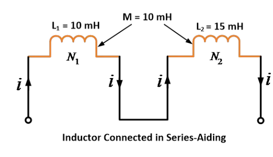
Solution:
Given data: L1 = 10 mH, L2 = 15 mH and M = 10 mH
According to series aiding formula,
Thus, by using the equation, we get the equivalent inductance 45 mH when they are connected in series aiding.
Example 2
Two coils have self-inductances of 10 mH and 15 mH and mutual inductance between two coils is 10 mH. Find the equivalent inductance when they are connected in series opposing.
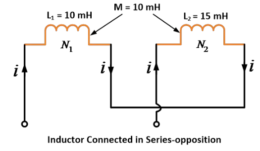
Solution:
Given data: L1 = 10 mH, L2 = 15 mH and M = 10 mH
According to series opposition formula,
Thus, by using the equation, we get the equivalent inductance 5 mH when they are connected in series opposing.
Inductors in Parallel Formula
How to add inductors in parallel
The two inductors can be connected in parallel such that
The mutually induced emf assists the self-induced EMFs i.e., parallel aiding connection
The mutually induced emf opposes the self-induced EMFs i.e., parallel opposing connection
Parallel-aiding (Cumulative) Connection(mutually induced emf assists the self-induced EMFs)
When two inductors are connected in parallel aiding, the mutually induced emf assists the self-induced EMFs as shown in the figure below.
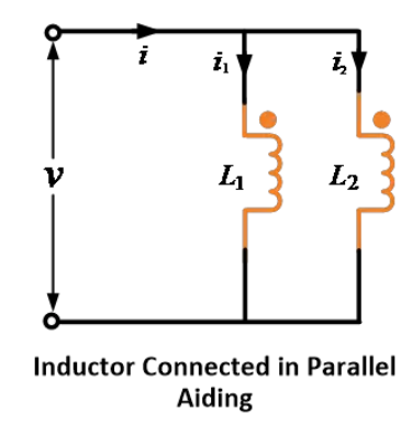
Let i1 and i2 be the currents flowing through inductors L1 and L2 and I be the total current.
Thus,
Therefore,
In each inductor, there will be two EMFs induced. One due to self-induction and the other due to mutual induction.
Since the inductors are connected in parallel, the EMFs are equal.
Therefore,
Now, put equation (9) in equation (8), we get,
If ![]() is the equivalent inductance of the parallel-connected inductors, the emf induced in it will be
is the equivalent inductance of the parallel-connected inductors, the emf induced in it will be
This is equal to the emf induced in any one coil i.e.,
Substitute the value of ![]() from equation (10) in to equation (13), we get,
from equation (10) in to equation (13), we get,
Now, equating equation (11) to equation (14),
The above equation gives the equivalent inductance of two inductors connected in parallel-aiding or cumulative connection.
If there is no mutual inductance between the two coils (i.e., M = 0), then,
Parallel Opposition (Differential) Connection (mutually induced emf opposes the self-induced EMFs)
When two inductors are connected in parallel opposition, the mutually induced emf opposes the self-induced EMFs.
As shown in the image below the two inductors are connected in parallel opposition or differentially.
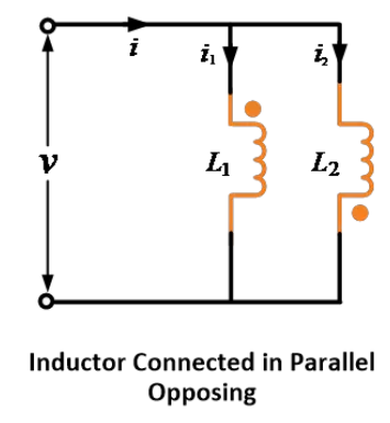
In a similar way to the parallel-aiding connection, it can be proved that,
The above equation gives the equivalent inductance of two inductors connected in parallel opposition or differential connection.
If there is no mutual inductance between the two coils (i.e., M = 0), then,
Example 1
Two inductors have self-inductances of 5 mH and 10 mH and mutual inductance between the two is 5 mH. Find the equivalent inductance when they are connected in parallel aiding.
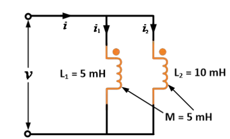
Solution:
Given data: L1 = 5 mH, L2 = 10 mH and M = 5 mH
According to parallel aiding formula,
Thus, by using the equation, we get the equivalent inductance 5 mH when they are connected in parallel aiding.
Example 2
Two inductors have self-inductances of 5 mH and 10 mH and mutual inductance between the two is 5 mH. Find the equivalent inductance when they are connected in parallel opposing.
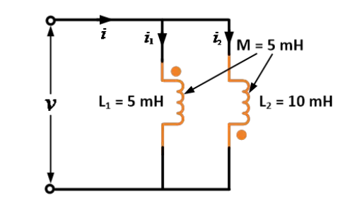
Solution:
Given data: L1 = 5 mH, L2 = 10 mH and M = 5 mH
According to parallel opposing formula,
Thus, by using the equation, we get the equivalent inductance 1 mH when they are connected in parallel opposing.
Coupling Inductors
When the magnetic field of one inductor (coil) cuts or links the turns of another neighboring inductor, the two inductors are said to be magnetically coupled. Due to coupling inductors or coils, a mutual inductance exists between the two coils.
In coupled circuits, the energy transfer takes place from one circuit to another when either of the circuits is energized. A two-winding transformer, an autotransformer, and an induction motor are examples of magnetically coupled inductors or coils, or circuits.
Consider two magnetically coupled inductors or coils 1 and 2 having inductances L1 and L2 respectively. Let M be the mutual inductance between the two coils.
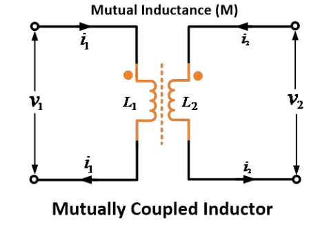
The effect of mutual inductance is to either increase (L1 + M and L2 + M) or decrease (L1 – M and L2 – M) the inductance of the two coils, this is depending on the arrangement of the two coils or inductors.
When the two coils are so arranged that their fluxes aid each other, then the inductance of each coil is increased by M i.e., it becomes L1 + M for coil 1 and L2 + M for coil 2. It is because the total flux linking each coil is more than its own flux.
When the two coils are so arranged that their fluxes oppose, then the inductance of each coil is decreased by M i.e., it becomes L1 – M for coil 1 and L2 – M for coil 2. It is because the total flux linking each coil is less than its own flux.
Mutual Inductance Formula
We know that any change of current in one coil is always accomplished by the production of mutually induced e.m.f. in the second coil.
Mutual inductance is defined as the ability of one coil (or circuit) to produce an e.m.f. in a nearby coil (or circuit) by induction when the current in the first coil changes.
In other words, the property of two coils by virtue of which each opposes any change of current flowing in the other is called mutual inductance between the two coils. This opposition occurs because a changing current in one coil produces mutually induced e.m.f. in the other coil which opposes a change of current in the first coil.
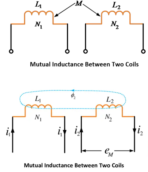
Mutual inductance (M) may be defined as the flux-linkages of a coil per unit current in the other coil.
Mathematically,
Where,
![]() = Current in first coil
= Current in first coil
![]() = Flux linking the second coil
= Flux linking the second coil
![]() = No. of turns on second coil
= No. of turns on second coil
Mutual inductance between two coils is 1 henry if current changing at the rate of 1 ampere per second in one coil induces an e.m.f. of 1 V in the other coil.
Coefficient of Coupling
The coefficient of coupling (k) between two coils is defined as the fraction of magnetic flux produced by the current in one coil that links the other.
The coefficient of coupling is an important parameter for coupled circuits to determine the amount of coupling between the inductively coupled coils.
Mathematically, the coefficient of coupling can be expressed as,
Where,
L1 is the self-inductance of the first coil
L2 is the self-inductance of the second coil
M is the mutual inductance between two coils
The coupling coefficient is depending on the mutual inductance between two coils. If the coupling coefficient is higher so the mutual inductance will be higher. Two inductively coupled coils are linked using the magnetic flux.
When the entire flux of one coil links the other, the coefficient of coupling is 1 (i.e., 100%), then coils are said to be tightly coupled.
If only half the flux set up in one coil links the other, the coefficient of coupling is 0.5 (i.e., 50%), then coils are said to be loosely coupled.
If the flux of one coil does not at all link with the other coil, the coefficient of coupling is 0, the coils are said magnetically isolated from each other.
The coefficient of coupling will always be less than unity. It depends on the core materials used. For air core, the coupling coefficient can be 0.4 to 0.8 depending on the space between two coils and for iron or ferrite core it can be as high as 0.99.
Source: Electrical4u.
Statement: Respect the original, good articles worth sharing, if there is infringement please contact delete.
Electrical4U is dedicated to the teaching and sharing of all things related to electrical and electronics engineering.


