Grounding Conductor: What is it (And How Do You Calculate The Right Size)?
What is a Grounding Conductor?
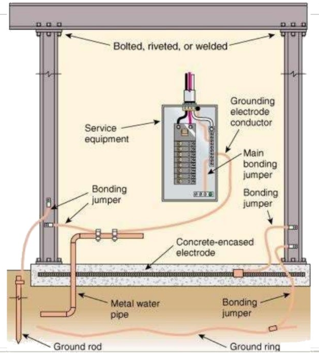
A grounding conductor is defined as a wire or conductor intentionally connected to the earth. The grounding conductor is commonly known as a “ground conductor” or “case ground.”
In most cases, the ground wire is connected with a case or outer part of the electrical box, appliances, or tools. Hence, the grounding conductor is also known as case ground.
The grounding conductor is used for safety purposes. In normal conditions, the grounding wire does not carry current.
Under a fault condition, the grounding wire provides a low resistance path to the current. And it provides an alternate path to current under-fault conditions.
Hence, the current will flow through a ground conductor instead of a human body or internal part of the equipment.
The term “grounding conductor” is different from the “grounded conductor.” The term “grounded conductor” is correctly referred to as “grounded neutral conductor.”
But it is commonly referred to as a “grounded conductor” or “neutral conductor.”
The grounded conductor is used to complete the path of a circuit. Under normal conditions, the current will flow through the grounded conductor to complete the path.
What Color Wire is a Grounding Conductor?
The grounding conductor does not require insulation. It can be installed as a bare conductor. And if the insulated wire is used as a grounding conductor, the color of this conductor is green or green-yellow stripes.
According to IEC-60446, AS/NZS 3000:2007 3.8.3, and BS-7671, the color code for grounding conductors is green-yellow stripes.
In Brazil, India, and Canada, only green color is used for grounding conductors.
How to Calculate the Size of a Grounding Conductor
The grounding conductor is used to provide a low-impedance fault current path that reduces electrical equipment to near-zero electrical potential (voltage).
As a thumb rule, the size of a grounding conductor should not be less than 25% of the capacity of the phase conductor or over-current device.
According to NEC (National Electrical Code Academic and Science), a minimum size of a grounding conductor is decided as per the below table.
| NEC Table 250.122 | ||
| Rating or setting of automatic overcurrent device in the circuit ahead of equipment, conduit, etc. Not Exceeding (Ampere) | Size (AWG or kcmil) | |
| Copper | Aluminum or copper-clad aluminum | |
| 15 | 14 | 12 |
| 20 | 12 | 10 |
| 60 | 10 | 8 |
| 100 | 8 | 6 |
| 200 | 6 | 4 |
| 300 | 4 | 2 |
| 400 | 3 | 1 |
| 500 | 2 | 1/0 |
| 600 | 1 | 2/0 |
| 800 | 1/0 | 3/0 |
| 1000 | 2/0 | 4/0 |
| 1200 | 3/0 | 250 |
| 1600 | 4/0 | 350 |
| 2000 | 250 | 400 |
| 2500 | 350 | 600 |
| 3000 | 400 | 600 |
| 4000 | 500 | 750 |
| 5000 | 700 | 1200 |
| 6000 | 800 | 1200 |
Source: Electrical4u
Statement: Respect the original, good articles worth sharing, if there is infringement please contact delete.
Electrical4U is dedicated to the teaching and sharing of all things related to electrical and electronics engineering.
