Grounding Conductor: What is it and how Do You Calculate it?
The method of connecting non-current carrying portions to earth or ground, such as the metallic frame of an electrical device or certain electrical components of a power system, such as the neutral point of star-connected system, is known as grounding, also referred to as earthing.
To avoid accidents & damage to the system’s equipment, electrical systems should always be grounded.
This post will discuss grounding conductors and how to determine the appropriate size for a grounding conductor based on the demand.
What is meant by the term “Grounding Conductor”?
In terms of an electrical system, the term “grounding conductor” refers to a wire or conductor that has been specifically linked to the ground (or) earth. The earth wire, ground wire, and grounding conductor are all other names for the same component.
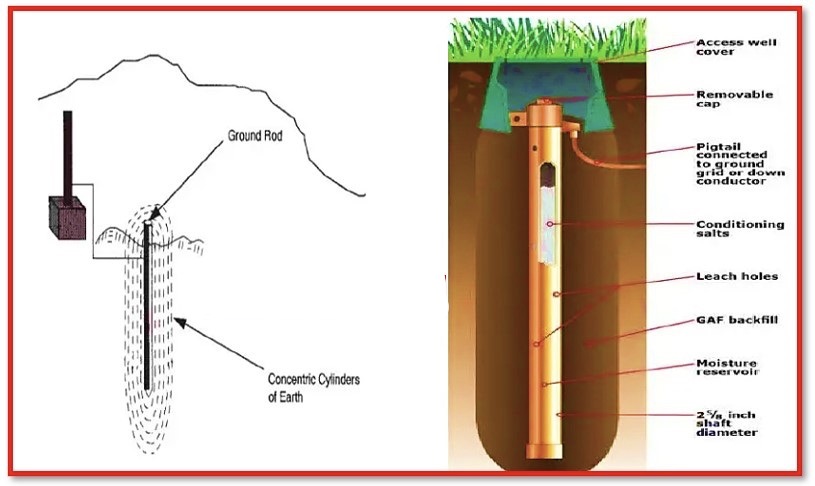
The casing or exterior metallic body of an electrical device is often linked to one end of the grounding conductor, while the other end is attached to the ground. The grounding conductor is then connected to the earth. The protection against accidents & damages that might be incurred as a result of flaws in the functioning of the electrical systems is the major objective of the grounding conductor. When everything is working as it should, the ground wire does not have any electricity flowing through it.
The grounding conductor is chosen in such a way that it is able to provide a path with very low resistance for flow of strong electric currents when the conditions are not optimum. As a result, the grounding conductor gives the flow of fault current an alternative path with a low resistance.
Therefore, when there is a problem with an electrical appliance, leakage currents will flow through the appliance’s metallic body. Leakage currents could flow via the ground wire if installed a grounding conductor that was connected between the appliance & earth. This would prevent the leakage currents from flowing through a person’s body (or) other non current carrying portions of the appliance.
Colour Coding of the Grounding Conductor
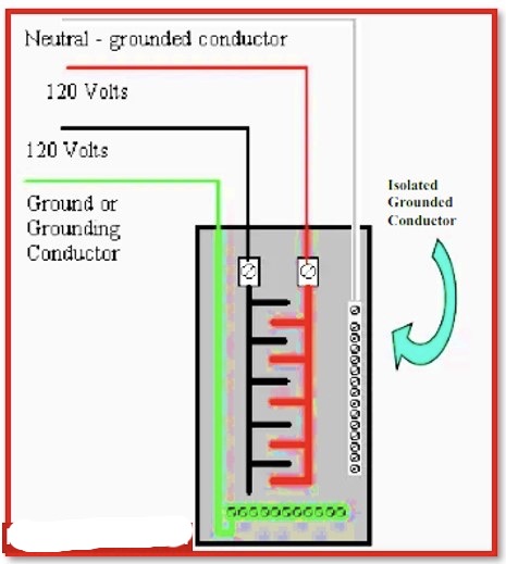
The grounding conductor is almost always an uncovered wire, implying that it does not have an insulating covering of any type or colour. This is the condition in a large number of circumstances.
However, the insulated wire is used to be a grounding conductor in a variety of applications; therefore, the colour of the insulation coating of this wire are required to be green or green and yellow stripes.
The colour of the insulating coating of wire that is used as a grounding conductor is specified to have green-yellow stripes in a number of different standards. These standards include
IEC-60446,
BS-7671, and
AS/NZS 3000:2007 3.8.3, amongst others.
On the other end, as a grounding conductor in nations such as
India,
Canada, and
Brazil,
the grounding conductor wire with the green-coloured insulation is used.
Calculation for Sizing a Grounding Conductor
The function of the ground conductor is to provide a path for the flow of the electric current that has an extremely low impedance when a fault situation is present.
As a result of this, it brings the voltage of the housing or body of an electrical equipment down to zero. Because of this, it is necessary to choose a wire of an appropriate size for grounding conductor for a specific application, and the size of the wire should be determined by the fault current rating of the system.
When selecting the size of a grounding conductor for use in real-world applications, it is standard procedure to follow the rule that the conductor’s current capacity cannot be less than 25% of the capacity of the phase conductor or of the overcurrent device.
The National Electrical Code (NEC) provides the following table, which supports in determining the minimum size of the grounding conductor that must be used.
| NEC Table 250.122: Minimum Size of Grounding Conductor for Equipment | |||
|---|---|---|---|
| Serial Number | Setting of an Automatic Over Current Device in the Circuit Before Equipment, Conduit, etc., Must Not Exceed (Amps) | Size of the Conductor (AWG or kcmil) | |
| Copper Wire Size | Aluminium (or) Copper-Clad Aluminium | ||
| 1 | 15 | 14 -AWG | 12-AWG |
| 2 | 20 | 12 | 10 |
| 3 | 60 | 10 | 8 |
| 4 | 100 | 8 | 6 |
| 5 | 200 | 6 | 4 |
| 6 | 300 | 4 | 2 |
| 7 | 400 | 3 | 1 |
| 8 | 500 | 2 | 1/0 |
| 9 | 600 | 1 | 2/0 |
| 10 | 800 | 1/0 | 3/0 |
| 11 | 1000 | 2/0 | 4/0 |
| 12 | 1200 | 3/0 | 250-kcmil |
| 13 | 1600 | 4/0 | 350 |
| 14 | 2000 | 250-kcmil | 400 |
| 15 | 2500 | 350 | 600 |
| 16 | 3000 | 400 | 600 |
| 17 | 4000 | 500 | 750 |
| 18 | 5000 | 700 | 1200 |
| 19 | 6000 | 800 | 1200 |
Difference Between a Grounding Conductor and a Grounded Conductor
In the technical terms, grounding conductor & grounded conductor, both of these names refer to the same phenomenon and explains different functions.
There is always a neutral point present in a circuit that has three phases and three wires linked in a star configuration. When the current in each of the three phases is equal, the potential at the neutral point is equal to zero.
However, under fault conditions, the phase current fails to continue to remain equal.
Under fault conditions, the voltage develops at neutral point, and the nature of the fault determines how the voltage manifests itself at the neutral point.
In order to ensure the safety of the equipment, the neutral point is wired up to the earth so that any fault current may be transmitted to the ground.
The term “grounded conductor” refers to the wire that makes the connection between the ground and the neutral of the supply system. Other names for this wire are “grounded neutral conductor” and “neutral conductor.”
When operating in normal conditions with single-phase loads, the neutral conductor of a 3-phase 4-wire system is the one that carries the current.
The following is the formula for determining the size of the ground conductor:
S= (Ig /k) x (√t)
Where,
S – Cross sectional area of bare conductor in mm²
1g- Ground Fault current in Amps
t –FaultDuration in Seconds
k – Current density of conductor in Amp/mm²
k for Copper– 205 A/mm²
k for Aluminium – 126 A/mm²
k for Steel (or) GI – 80 A/mm²
Statement: Respect the original, good articles worth sharing, if there is infringement please contact delete.
As an electrical engineer with 5 years of experience, I focus on transformer and circuit breaker reliability in 110/33-11kV and 33/11kV substations. I am a professional electrical engineer with experience in transformer service and maintenance.

