Faraday’s Laws of Electromagnetic Induction: First & Second Law
What is Faraday’s Law
Faraday’s law of electromagnetic induction (referred to as Faraday’s law) is a basic law of electromagnetism predicting how a magnetic field will interact with an electric circuit to produce an electromotive force (EMF). This phenomenon is known as electromagnetic induction.
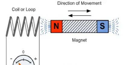
Faraday’s law states that a current will be induced in a conductor which is exposed to a changing magnetic field. Lenz’s law of electromagnetic induction states that the direction of this induced current will be such that the magnetic field created by the induced current opposes the initial changing magnetic field which produced it. The direction of this current flow can be determined using Fleming’s right-hand rule.
Faraday’s law of induction explains the working principle of transformers, motors, generators, and inductors. The law is named after Michael Faraday, who performed an experiment with a magnet and a coil. During Faraday’s experiment, he discovered how EMF is induced in a coil when the flux passing through the coil changes.
Faraday’s Experiment
In this experiment, Faraday takes a magnet and a coil and connects a galvanometer across the coil. At starting, the magnet is at rest, so there is no deflection in the galvanometer i.e the needle of the galvanometer is at the center or zero position. When the magnet is moved towards the coil, the needle of the galvanometer deflects in one direction.

When the magnet is held stationary at that position, the needle of galvanometer returns to zero position. Now when the magnet moves away from the coil, there is some deflection in the needle but opposite direction, and again when the magnet becomes stationary, at that point respect to the coil, the needle of the galvanometer returns to the zero position. Similarly, if the magnet is held stationary and the coil moves away, and towards the magnet, the galvanometer similarly shows deflection. It is also seen that the faster the change in the magnetic field, the greater will be the induced EMF or voltage in the coil.
Position of magnet |
Deflection in galvanometer |
Magnet at rest |
No deflection in the galvanometer |
Magnet moves towards the coil |
Deflection in galvanometer in one direction |
Magnet is held stationary at same position (near the coil) |
No deflection in the galvanometer |
Magnet moves away from the coil |
Deflection in galvanometer but in the opposite direction |
Magnet is held stationary at the same position (away from the coil) |
No deflection in the galvanometer |
Conclusion: From this experiment, Faraday concluded that whenever there is relative motion between a conductor and a magnetic field, the flux linkage with a coil changes and this change in flux induces a voltage across a coil.
Michael Faraday formulated two laws on the basis of the above experiments. These laws are called Faraday’s laws of electromagnetic induction.
Faraday’s First Law
Any change in the magnetic field of a coil of wire will cause an emf to be induced in the coil. This emf induced is called induced emf and if the conductor circuit is closed, the current will also circulate through the circuit and this current is called induced current.
Method to change the magnetic field:
By moving a magnet towards or away from the coil
By moving the coil into or out of the magnetic field
By changing the area of a coil placed in the magnetic field
By rotating the coil relative to the magnet

Faraday’s Second Law
It states that the magnitude of emf induced in the coil is equal to the rate of change of flux that linkages with the coil. The flux linkage of the coil is the product of the number of turns in the coil and flux associated with the coil.
Faraday Law Formula

Consider, a magnet is approaching towards a coil. Here we consider two instants at time T1 and time T2.
Flux linkage with the coil at time,

Flux linkage with the coil at time,

Change in flux linkage,

Let this change in flux linkage be,

So, the Change in flux linkage

Now the rate of change of flux linkage

Take derivative on right-hand side we will get

The rate of change of flux linkage

But according to Faraday’s law of electromagnetic induction, the rate of change of flux linkage is equal to induced emf.

Considering Lenz’s Law.
Where:
Flux Φ in Wb = B.A
B = magnetic field strength
A = area of the coil
How To Increase EMF Induced in a Coil
By increasing the number of turns in the coil i.e N, from the formulae derived above it is easily seen that if the number of turns in a coil is increased, the induced emf also gets increased.
By increasing magnetic field strength i.e B surrounding the coil- Mathematically, if magnetic field increases, flux increases and if flux increases emf induced will also get increased. Theoretically, if the coil is passed through a stronger magnetic field, there will be more lines of force for the coil to cut and hence there will be more emf induced.
By increasing the speed of the relative motion between the coil and the magnet – If the relative speed between the coil and magnet is increased from its previous value, the coil will cut the lines of flux at a faster rate, so more induced emf would be produced.
Applications of Faraday’s Law
Faraday law is one of the most basic and important laws of electromagnetism. This law finds its application in most of the electrical machines, industries, and the medical field, etc.
Power transformers function based on Faraday’s law
The basic working principle of the electrical generator is Faraday’s law of mutual induction.
The Induction cooker is the fastest way of cooking. It also works on the principle of mutual induction. When current flows through the coil of copper wire placed below a cooking container, it produces a changing magnetic field. This alternating or changing magnetic field induces an emf and hence the current in the conductive container, and we know that the flow of current always produces heat in it.
Electromagnetic Flow Meter is used to measure the velocity of certain fluids. When a magnetic field is applied to an electrically insulated pipe in which conducting fluids are flowing, then according to Faraday’s law, an electromotive force is induced in it. This induced emf is proportional to the velocity of fluid flowing.
Form bases of Electromagnetic theory, Faraday’s idea of lines of force is used in well known Maxwell’s equations. According to Faraday’s law, change in magnetic field gives rise to change in electric field and the converse of this is used in Maxwell’s equations.
It is also used in musical instruments like an electric guitar, electric violin, etc.
Statement: Respect the original, good articles worth sharing, if there is infringement please contact delete.
Electrical4U is dedicated to the teaching and sharing of all things related to electrical and electronics engineering.
