NORTON’S THEOREM

Norton’s Theorem is a principle in electrical engineering that allows the complex impedance of an electric circuit to be reduced to a single equivalent impedance. It states that any linear, two-terminal electrical network can be represented by an equivalent circuit consisting of a single current source in parallel with a single impedance. The current of the source is the short-circuit current of the network, and the impedance is the impedance seen looking into the circuit with the current source removed and the terminals open-circuited. Norton’s Theorem is named after the American engineer E. L. Norton, who first proposed it in the early 20th century.
STATEMENT OF NORTON’S THEOREM:
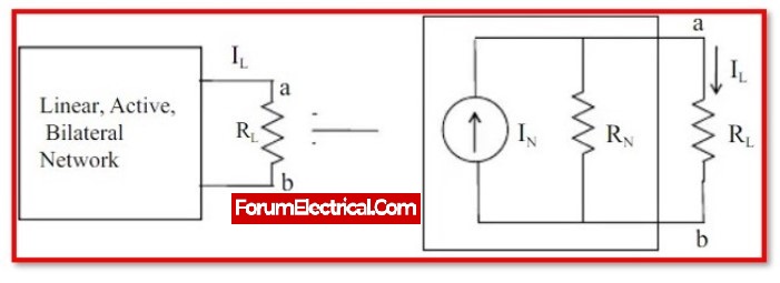
Any linear, active, bidirectional dc network with a number of voltage sources and/or current sources with resistances can be substituted by a simple equivalent circuit with a single current source (IN) in parallel with a single resistance (RN).

Where,
(IN) is the Norton’s equivalent current across terminals a-b.
(RN) is the Norton’s equivalent resistance across terminals a-b.
Similar to Thevenin’s theorem, except that the voltage source is gradually replaced by a current source
Find the Thevenin equivalent circuit first, then convert it to an equivalent current source.
The Norton equivalent resistance:
RN =RTH
The Norton equivalent current:
IN = VTH/RTH
IN denotes the current flowing in the short circuit connected across the terminals where the Norton equivalent circuit is required.
The Norton equivalent circuit is a useful tool for analyzing and designing electrical circuits because it allows the circuit to be represented by a single, simplified model. This makes it much easier to understand the behavior of the circuit and to calculate its response to different input signals.
To determine the Norton equivalent of a circuit, the following steps can be followed:
Remove all independent sources from the circuit and open the terminals.
Determine the impedance looking into the terminals with the sources removed. This is the Norton impedance.
Restore the sources to the circuit and determine the short-circuit current at the terminals. This is the Norton current.
The Norton equivalent circuit is a current source with a value equal to the Norton current in parallel with an impedance equal to the Norton impedance.
Norton’s Theorem is only applicable to linear, two-terminal networks. It is not applicable to nonlinear circuits or circuits with more than two terminals.
Statement: Respect the original, good articles worth sharing, if there is infringement please contact delete.
As an electrical engineer with 5 years of experience, I focus on transformer and circuit breaker reliability in 110/33-11kV and 33/11kV substations. I am a professional electrical engineer with experience in transformer service and maintenance.


