Electric Current: What is it?
What is Electric Current?
Electric current is defined as a stream of charged particles—such as electrons or ions—moving through an electrical conductor or space. It is the flow rate of electric charge through a conducting medium with respect to time. Electric current is expressed mathematically (e.g. in formulas) using the symbol “I” or “i”. The unit for current is is ampere or amp. This is represented by A.
Mathematically, the flow rate of charge with respect to time can be expressed as,
In other words, a stream of charged particles flowing through an electrical conductor or space is known as an electric current. The moving charged particles are called charge carriers which may be electrons, holes, ions, etc.
The flow of current depends on the conductive medium. For example:
In the conductor, the flow of current is due to electrons.
In semiconductors, the flow of current is due to electrons or holes.
In an electrolyte, the flow of current is due to ions and
In plasma—an ionized gas, the flow of current is due to ions and electrons.
When an electrical potential difference is applied between two points in a conductive medium, an electric current starts flowing from higher potential to lower potential. The higher the voltage or potential difference, the more the current flows between two points.
If two points in a circuit are at the same potential, then the current cannot flow. The magnitude of a current depends on the voltage or potential difference between two points. Hence, we can say the current is the effect of voltage.
Electric current can produce electromagnetic fields, which are used in inductors, transformers, generators, and motors. In electric conductors, current causes resistive heating or joule heating which makes light in an incandescent lamp.
A time-varying electric current produces electromagnetic waves, which are used in telecommunications to broadcast data.
AC vs DC Current
Based on the flow of charge, the electric current is classified into two types, i.e., alternating current (AC) and direct current (DC).
AC Current
The flow of electric charge in a periodically reverse direction is known as alternating current (AC). AC is also referred to as “AC Current”. Although this is technically saying the same thing twice “AC Current Current”.
An alternating current changes its direction at periodic intervals.
The alternating current starts from zero, rises to a maximum, decreases to zero, then reverses and reaches a maximum in the opposite direction, then again returns to the original value and repeats this cycle infinitely.
The type of alternating current waveform may be sinusoidal, triangular, square, sawtooth, etc.
The particularity of the waveform doesn’t matter—so long as it is a repeating waveform.
That said in most electrical circuits, the typical waveform of alternating current is a sine wave. A typical sine waveform that you might see as an alternating current is shown in the image below.
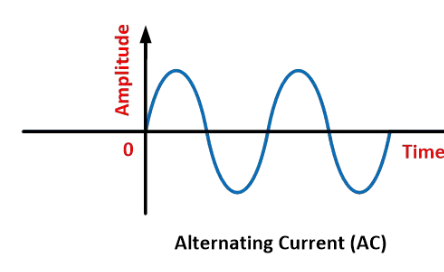
An alternator can generate an alternating current. The alternator is a special type of electrical generator designed to generate alternating current.
AC electric power is widely used in industrial and residential applications.
DC Current
The flow of electric charge in only one direction is known as direct current (DC). DC is also referred to as “DC Current”. Although this is technically saying the same thing twice “Direct Current Current”.
As DC flows only in one direction; hence it is also referred to as unidirectional current. A waveform of a direct current is shown in the image below.
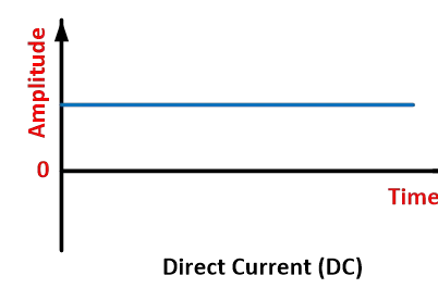
DC can be generated by batteries, solar cells, fuel cells, thermocouples, commutator-type electrical generators, etc. An alternating current can be converted to direct current by using a rectifier.
DC electric power is generally used in low-voltage applications. Most electronic circuits need a DC power supply.
What is Electric Current Measured In (Current Units)?
The SI unit for current is ampere or amp. This is represented by A. Ampere, or amp is the base SI unit of electric current. The unit ampere is named in honor of the great physicist Andrew Marie Ampere.
In the SI system, 1 ampere is the flow of electric charge between two points at the rate of one coulomb per second. Thus,
Hence current is also measured in coulomb per second or C/S.
Electric Current Formula
The basic formulas for current are:
The relationship between Current, Voltage, and Resistance (Ohm’s Law)
The relationship between Current, Power, and Voltage
The relationship between Current, Power, and Resistance
These relationships are summarised in the image below.
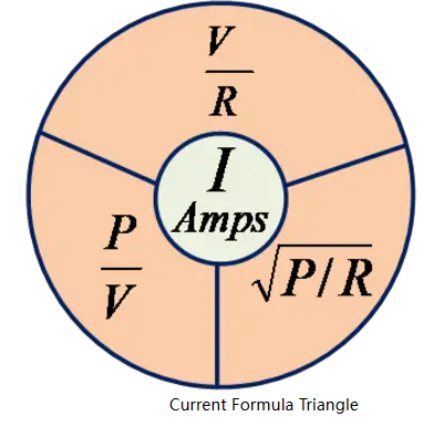
Current Formula 1 (Ohm’s Law)
According to to Ohm’s law,
Thus,
Example
As shown in the below circuit, a supply voltage of ![]() is applied across the resistance of
is applied across the resistance of ![]() . Determine the current flowing through the resistor.
. Determine the current flowing through the resistor.
Solution:
Given Data: ![]()
According to Ohm’s law,
Thus, by using the equation, we get the current flowing through the resistor is ![]() .
.
Current Formula 2 (Power and Voltage)
The power transferred is the product of supply voltage and electric current.
Thus, we get current equals the power divided by voltage. Mathematically,
Where ![]() stands for amperes or amps (the units for electric current).
stands for amperes or amps (the units for electric current).
Example
As shown in the circuit below, a supply voltage of ![]() is applied to a
is applied to a ![]() lamp. Determine the current taken by the
lamp. Determine the current taken by the ![]() lamp.Solution:
lamp.Solution:
Given Data: ![]()
According to formula,
Thus, using the equation above we get the current taken by ![]() lamp is equal to
lamp is equal to ![]() .
.
Current Formula 3 (Power and Resistance, Ohmic Loss, Resistive Heating)
We know that, ![]()
Now substituting Ohm’s law ![]() into the above equation we get,
into the above equation we get,
Thus, the current is the square root of the ratio of power and resistance. Mathematically, the formula for this is equal to:
Example
As shown in the below circuit, determine the current taken by ![]() ,
, ![]() lamp
lamp
Solution:
Given Data: ![]()
According to the relationship between current, power, and resistance shown above:
Thus, using the equation, we get the current taken by ![]() ,
, ![]() lamp is
lamp is ![]() .
.
Dimensions of Current
Dimensions of current in terms of mass (M), length (L), time (T), and ampere (A) is given by ![]() .
.
Current (I) is a representation of the coulomb per second. Thus,
Conventional Current vs Electron Flow
There is a slight misconception about conventional current flow and electron flow. Let’s try to understand the difference between the two.
The particles that carry electric charge through conductors are mobile or free electrons. The direction of an electric field within a circuit is, by definition, the law that positive test charges are pushed. Thus, these negative charge particles, i.e., electrons, flow in the opposite direction to the electric field.
According to electron theory, when voltage or potential difference is applied across the conductor, charged particles flow through the circuit, which constitutes an electric current.
These charged particles flow from higher potential to lower potential, i.e., from a positive terminal to the battery’s negative terminal through an external circuit.
But, in a metallic conductor, the positively charged particles are held in a fixed position, and the negatively charged particles, i.e., electrons, are free to move. In semiconductors, the flow of charged particles can be positive or negative.
A flow of positive charge carriers and negative charge carriers in the opposite direction has the same effect in the electric circuit. Since the flow of current is due to either positive or negative charges, or both, a convention is required for the current direction that is independent of the types of charge carriers.
The direction of conventional current is considered the direction in which positive charge carriers flow, i.e., from higher potential to lower potential. Therefore, negative charge carriers, i.e., electrons flow in the opposite direction of conventional current flow, i.e., from lower potential to higher potential. Hence, the conventional current and electron flow go in opposite directions which is shown in the image below.

Conventional Current: The flow of positive charge carriers from a positive terminal to a negative terminal of the battery is known as conventional current.
Electron Flow: The flow of electrons is termed electron current. The flow of negative charge carriers – i.e., electrons – from a negative terminal to a positive terminal of the battery is known as electron flow. Electron flow is the opposite of conventional current flow.
The direction of conventional current and electron flow is shown in the image below.
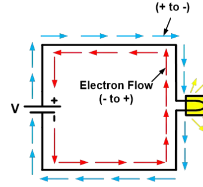
Convection Current vs Conduction Flow
Convection Current
A convection current refers to current flow through an insulating medium such as liquid, gas, or a vacuum.
Convection current does not require conductors to flow; hence it does not satisfy Ohm’s law. An example of a convection current is a vacuum tube in which electrons emitted by the cathode flow to the anode in a vacuum.
Conduction Current
The current that flows through any conductor is known as the conduction current. Conduction current requires the conductor to flow; hence it does satisfy Ohm’s law.
Displacement Current
Consider a resistor and capacitor are connected in parallel with voltage source V as shown in the below figure. The nature of current flow through the capacitor is different from that through the resistor.
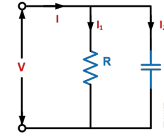
The voltage or potential difference across the resistor produces a continuous flow of current which is given by the equation,
This current is called a “conduction current.”
Now the current flow through the capacitor only when the voltage across the capacitor changes, which is given by the equation,
This current is called a “displacement current.”
Physically the displacement current is not a current as there is no flow of a physical quantity like a flow of charges.
How To Measure Current
In an electrical and electronic circuit, current measurement is an essential parameter that needs to be measured.
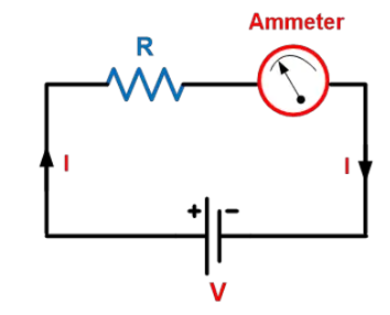
An instrument that can measure the electric current is called an ammeter. To measure current ammeter must connect in series with the circuit whose current is to be measured.
The measurement of current through the resistor by using an ammeter is shown in the below figure.
The electric current can also be measured using a galvanometer. The galvanometer gives both the direction and the magnitude of the electric current.
The current can be measured by detecting the magnetic field associated with the current without breaking the circuit. There are various instruments used to measure the current without breaking the circuit.
Current transformer (CT) (only measures AC)
Common Questions About Current
Let us study some common questions related to electric current.
What Uses an Electromagnet to Measure Electric Current?
A galvanometer is a measuring instrument that uses an electromagnet to measure electric current.
A galvanometer is an absolute instrument; it measures the electric current in terms of a tangent of deflection angle.
A galvanometer can measure the electric current directly, but this involves breaking the circuit; hence sometimes, it is inconvenient.
How Does an Electric Current Produce a Magnetic Force?
A current-carrying conductor placed in the magnetic field will experience a force since the current is nothing but the flow of charges.
Consider a current-carrying conductor with current flows through it, as shown in the below figure (a). According to Fleming’s right-hand rule; this current will produce a magnetic field in a clockwise direction.
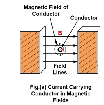
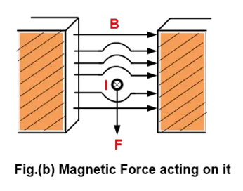
The result of a magnetic field of the conductor is that it will force the magnetic field above the conductor and waken it below.
The field lines are like stretched rubber bands; hence they will push the conductor in a downward direction, i.e., the force is downward, as shown in figure (b).
This example says that the current-carrying conductor in a magnetic field experiences a force. The following equation determines the magnitude of the magnetic force on a current-carrying conductor.
To Make an Electric Current Flow, It Is Necessary to Have
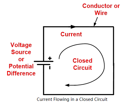
To make an electric current flow, it is necessary to have the following:
A potential difference which exists between the two points. If the two points in a circuit are at the same potential, the current cannot flow.
A voltage source or current source, such as a battery or cell that forces the free electrons which constitutes an electric current.
A conductor or wire which carries electric charges.
A circuit must be closed or complete. If circuits are open, the current cannot flow.
These are the conditions that are necessary to make an electric current flow. The image below shows a current passing in a closed circuit.
Which Best Describes a Difference Between Electric Current and Static Electricity
The main difference between electric current and static electricity is that the electrons or charges flow through the conductor in an electric current.
Whereas, in static electricity, the charges are rest and accumulated on the surface of the substance.
The electric current is due to the flow of electrons, whereas static electricity is due to the negative charges from one object to another.
The electric current generates only in the conductor, whereas static electricity generates both in the conductor or insulator.
How Does an Electric Current Affect a Magnetic Pole?
We know that when electric current flows, i.e., electric charge is in motion, it produces a magnetic field. If we keep the magnet in a magnetic field, it experiences a force.
For electric charges, i.e., electric current, like magnetic poles attract and opposite magnetic poles repel. So, we can say that electric current affects the magnetic pole via the magnetic field.
What Instrument Is Used to Measure Electric Current
An instrument that can measure the electric current is called an ammeter. The ammeter must connect in series with the circuit whose current is to be measured.
Other various instruments are also used to measure the electric current.
Hall effect current sensor transducers
Current transformer (CT) (Only measure AC)
Clamp-on meters
Shunt resistors
Magnetoresistive field sensors
Source: Electrical4u
Statement: Respect the original, good articles worth sharing, if there is infringement please contact delete.
Electrical4U is dedicated to the teaching and sharing of all things related to electrical and electronics engineering.
