How can we calculate the number of electrons per second flowing through a wire in a circuit?

Encyclopedia
10/08/2024

The number of electrons per second flowing through a wire in a circuit can be calculated from a known current value. Current is measured in amperes (Ampere, A), defined as 1 Coulomb (C) of charge flowing through a cross section of a wire per second. We know that the charge of 1 coulomb is equal to about 6.242 x 10^18 electrons.


Calculation formula


  • Current (I) : Current is measured in amperes (A) and represents the amount of charge passing through a cross section of a wire per unit time.


  • Number of electrons (N) : The number of electrons per second flowing through a section of a wire.


The formula is as follows:


  • N= (I x t) /qe

  • I is current (unit: ampere, A)

  • t is the time (in seconds, s), and in this calculation t=1 second

  • qe is the charge of a single electron (unit: coulomb, C), qe≈1.602×10⁻¹⁹ coulomb


The simplified formula is:


N = I / 1.602 x 10⁻¹⁹


Applied to practical circuits


  • Measuring current: First of all, you need to use an Ammeter to measure the current value in the circuit.


  • Determine the time: In this example, we set the time t=1 second, but if we need to count the number of electrons in other time periods, we need to adjust the time value accordingly.


  • Calculate the number of electrons: The measured current value is substituted into the above formula to calculate the number of electrons per second flowing through a section of the wire.


Practical application example


Suppose we need to calculate the number of electrons in an actual circuit with A current of 2 amps (I = 2 A), then:


N=2/1.602×10−19≈1.248×1019


This means that at a current of 2 amps, approximately 1.248 × 10^19 electrons are flowing through the wire every second.


Matters needing attention


  • Accuracy: There may be errors in the actual measurement, so the calculated result may be slightly different from the theoretical value.


  • Temperature and material: Differences in temperature and wire material also affect the conduction efficiency of the current, which in turn affects the calculation results.


  • Multiple electron streams: there may be multiple electron streams in the actual circuit at the same time, so the total number of electrons also needs to take these factors into account.


Through the above formula and steps, you can calculate the number of electrons per second flowing through a certain section of the wire in the circuit. This is important for understanding current strength and electron flow in circuits.


Encyclopedia

The Electricity Encyclopedia is dedicated to accelerating the dissemination and application of electricity knowledge and adding impetus to the development and innovation of the electricity industry.

One-Tap Energy Control: How Smart Apps Breathe Life into Your Home Storage System
As home energy storage evolves from "backup power" to "energy manager,"smart control appsare becoming the command center for households worldwide. More than a remote switch, it’s your intelligent brain for energy freedom and bill reduction—Scenario 1: Blackout? Zero-Second Switch, Safety at Your FingertipsA midnight storm knocks out grid power—your phone lights up: ‘Backup activated. 32-hour runtime secured.’With apps likeHi-Smart Energy(from Hi-Solar), you can:✅Rea
RW Energy
06/20/2025
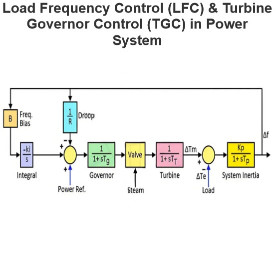
Load Frequency Control (LFC) & Turbine Governor Control (TGC) in Power System
Brief Introduction to Thermal Generating UnitsElectricity generation relies on both renewable and non - renewable energy resources. Thermal generating units represent a conventional approach to power production. In these units, fuels such as coal, nuclear energy, natural gas, biofuel, and biogas are combusted within a boiler.The boiler of a generating unit is an extremely complex system. In its simplest conception, it can be visualized as a chamber whose walls are lined with pipes, through which
Edwiin
06/06/2025
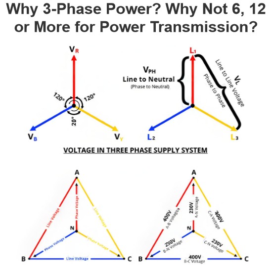
Why 3-Phase Power? Why Not 6, 12 or More for Power Transmission?
It is well-known that single-phase and three-phase systems are the most prevalent configurations for power transmission, distribution, and end-use applications. While both serve as fundamental power supply frameworks, three-phase systems offer distinct advantages over their single-phase counterparts.Notably, multi-phase systems (such as 6-phase, 12-phase, etc.) find specific applications in power electronics—particularly in rectifier circuits and variable frequency drives (VFDs)—wher
Edwiin
06/05/2025
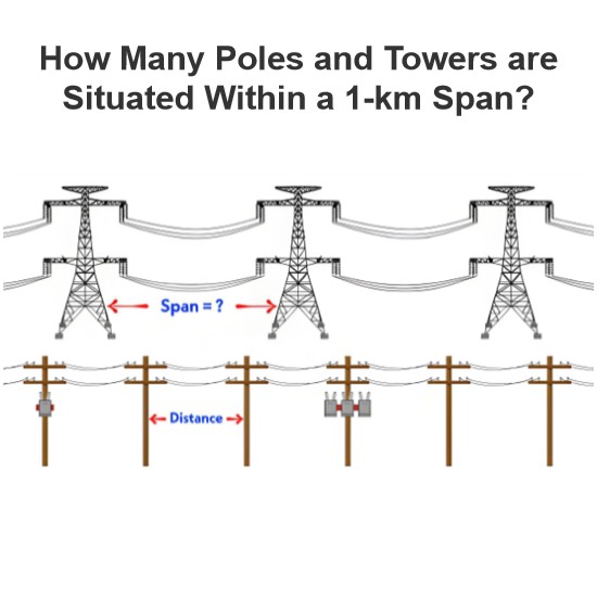
How Many Poles and Towers are Situated Within a 1-km Span?
The number of distribution poles and transmission towers within a 1-kilometer stretch of overhead lines varies significantly based on multiple factors, including voltage level, power line type, supporting structure, geographical location, local regulations, and specific grid requirements.In urban areas, distribution utility poles are typically positioned at closer intervals, while in rural regions, they are spaced farther apart. Additionally, the use of taller structures for higher-voltage trans
Edwiin
06/05/2025
Inquiry
Download
Experts Electrical is dedicated to serving the personnel in the global power industry.
Join Experts Electrical, not only can you discover power equipment and power knowledge, but also canhnd like - minded friends!